14 www.pridemobility.com J6 with NE, NE+, and Q-Logic Electronics Technical Troubleshooting Guide
5. Verify the inhibit program. The charger inhibit
“chrgInb” should be set to “ON” for NE electronics or
to “High Inhibit” for NE+ or Q-Logic electronics. See
figure 18 for NE electronics or figure 22 for NE+ or
Q-Logic electronics.
— If the inhibit is programmed incorrectly,
then reprogram
the inhibit and retest the system.
— If the power chair does not drive and the inhibit program
is correct,
then replace the power module (2) and retest
the system.
Joystick Error
Symptoms:
The batteries are fully charged.
All electrical components are properly connected.
An error code is displayed when the NE, NE+, or Q-
Logic joystick module (1) is powered on.
The joystick is in the neutral (centered) position when
the unit is powered on.
Diagnosis:
There is an input communications error.
Solution:
Use the following procedure to find the source of the error:
1. Check that the BUS cables and communication devices
are connected correctly. See diagram 5 or 6.
2. Measure resistance across connectors 3a and 3b of the
BUS cable extension (3). See figure 19.
— If the multimeter indicates an open for any of the
measurements, then replace the BUS cable extension
(3) and retest the system.
— If the multimeter indicates less than 1 ohm for all of the
measurements, then go to the next step.
3. If the power chair is equipped with multiple input
devices, then ensure there is a multiplier in the BUS line.
— If there is no multiplier, then contact Quantum
Technical Service for further troubleshooting help.
— If there is a multiplier on the BUS line, then go to the
next step.
4. Measure resistance on the multiplier BUS cable. See
figure 20.
— If the multimeter indicates an open for any of the
measurements, then replace the multiplier and retest the
system.
— If the multimeter indicates less than 1 ohm for all of the
measurements, then contact Quantum Technical
Service for further troubleshooting help.
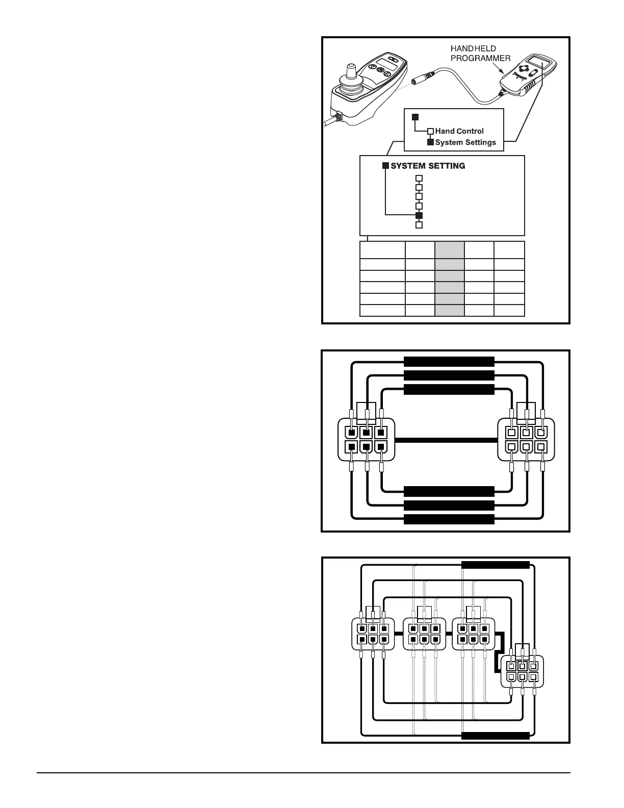
Figure 18. Inhibit (i2) Programming (NE Electronics)
i1 i2 i3
Active Off OffOn
On OnOnactiveH
OOO
proSel
Off OffOndrvInh
Off OffOnchrgInb
General Drive
Timing
Motors & Wheels
Battery
Inputs
Miscellaneous
PROGRAM
Figure 19. BUS Cable Extension (3)
123
456
1 2 3
4 5 6
3b
3a
Measure Resistance
Measure Resistance
Measure Resistance
Measure Resistance
Measure Resistance
Measure Resistance
Figure 20. Multiplier
123
456
1 2 3
4 5 6
1 2 3
4 5 6
1 2 3
4 5 6
Measure Resistance
Measure Resistance