18 www.pridemobility.com J6 with NE, NE+, and Q-Logic Electronics Technical Troubleshooting Guide
Motor/Brake Error
Symptoms:
The batteries are fully charged.
All electrical components are properly connected.
The power turns on but displays “Motor/Brake Error”
(NE or NE+ controllers) or a brake error (Q-Logic
controller). See table 1, 2, or 3.
Diagnosis:
There is a problem with one or both brakes and/or the wiring
between the motor, brakes, and the power module (2).
Solution:
Use the following procedure to find the source of the error:
1. Ensure both freewheel levers are in drive mode. Refer to
the freewheel operation label located on the power base.
2. Remove the seat. Refer to the power base owner’s
manual.
3. Remove the rear and center shrouds. See figure 3.
4. Disconnect the power module (2) from the module
mounting bracket. See figure 6.
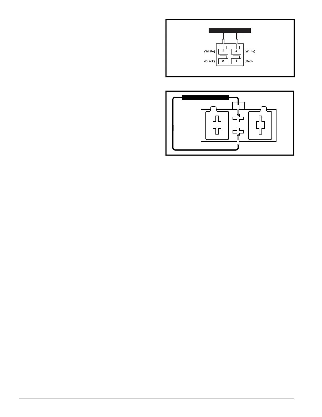
Figure 26. Connector 6a or 7a
Figure 27. Connector 8a or 9a
5. Unplug connector 6a from connector 8b.
See diagram 5 or 6
.
6. Measure resistance across the two white pins on connector 6a. See figure 26.
— If the multimeter indicates about 60 ohms, then plug connector 6a back into connector 8b and go to the next step.
— If the multimeter indicates an open, then replace the left brake assembly and retest the system.
7. Unplug connector 8a from connector 2b.
See diagram 5 or 6
.
8. Measure resistance across pin 3 and pin 4 on connector 8a. See figure 27.
— If the multimeter indicates about 60 ohms, then go to the next step.
— If the multimeter does not indicate about 60 ohms, then replace the left motor interface harness (8) and retest the
system.
9. Unplug connector 7a from connector 9b.
See diagram 5 or 6
.
10. Measure resistance across the two white pins on connector 7a. See figure 26.
— If the multimeter indicates about 60 ohms, then plug connector 7a back into connector 9b and go to the next step.
— If the multimeter indicates an open, then replace the right brake assembly and retest the system.
11. Unplug connector 9a from connector 2d.
See diagram 5 or 6
.
12. Measure resistance across pin 3 and pin 4 on connector 9a. See figure 27.
— If the multimeter indicates about 60 ohms, then replace the power module (2).
— If the multimeter does not indicate about 60 ohms, then replace the right motor interface harness (9) and retest the
system.