J6 with NE, NE+, and Q-Logic Electronics Technical Troubleshooting Guide www.pridemobility.com 17
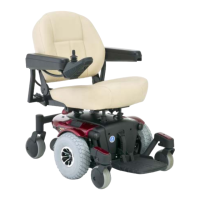
4. Measure resistance across the red and black pins on
connector 6a. See figure 23.
— If the multimeter does not indicate about 0.5 to 1.5
ohms, then go to the next step.
— If the multimeter indicates about 0.5 to 1.5 ohms,
then plug
connector 6a back into connector 8b and go to
step 6
.
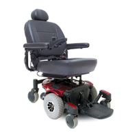
5. Remove the brushes from the left motor (6) and inspect
them.
See figure 24
.
— If the motor brushes are worn below 0.25 in. or they are
physically damaged, then replace the motor brushes and
retest the system.
— If the motor brushes are not worn below 0.25 in. and are
not physically damaged, then replace the left motor (6)
and retest the system.
From step 4
6. Disconnect the power module (2) from the module
mounting bracket. See figure 6.
7. Unplug connector 8a from connector 2b.
See diagram 5
or 6
.
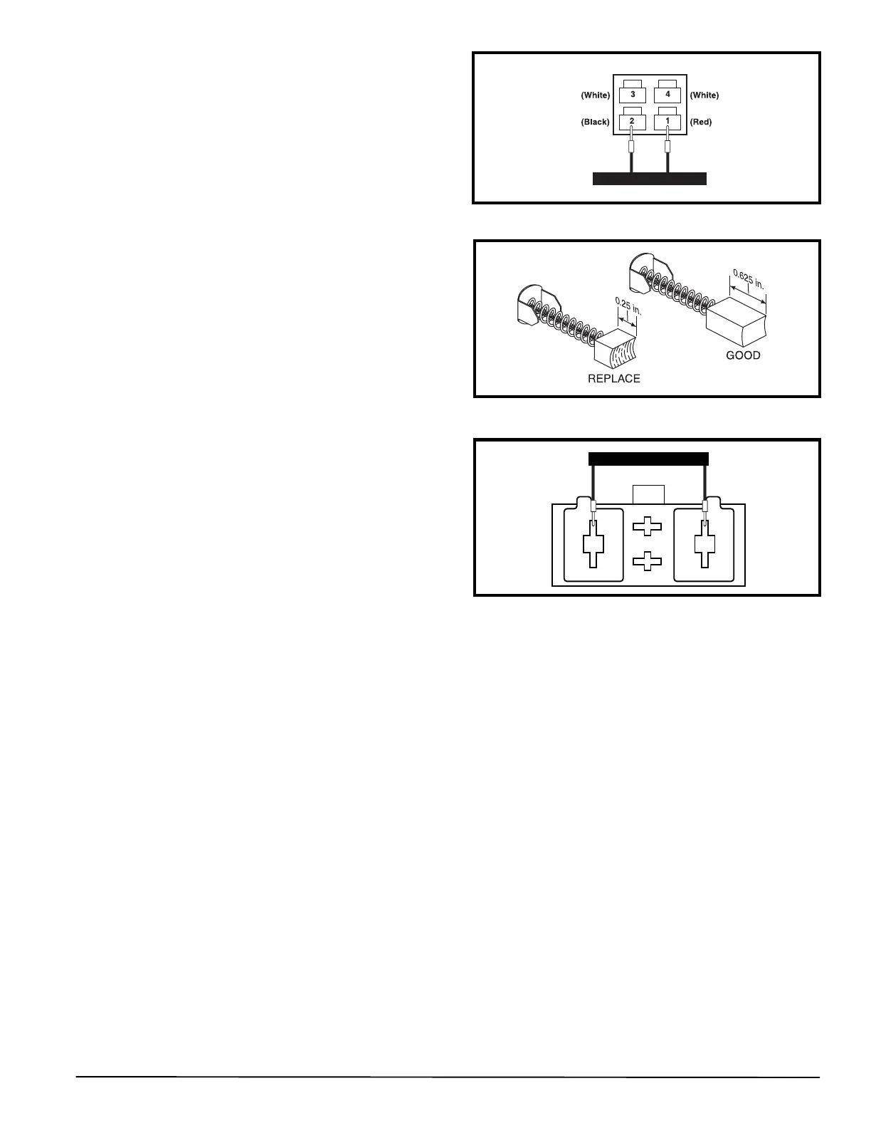
8. Measure resistance across pin 1 and pin 2 on connector
8a. See figure 25.
— If the multimeter does not indicate about 0.5 to 1.5
ohms, then replace the left motor interface harness (8)
and retest the system.
— If the multimeter indicates about 0.5 to 1.5 ohms, then
go to the next step.
Figure 23. Connector 6a or 7a
Figure 24. Motor Brushes
Figure 25. Connector 8a or 9a
9. Unplug connector 7a from connector 9b.
See diagram 5 or 6
.
10. Measure resistance across the red and black pins on connector 7a. See figure 23.
— If the multimeter does not indicate about 0.5 to 1.5 ohms, then go to the next step.
—
If the multimeter indicates about 0.5 to 1.5 ohms
, then plug
connector 7a back into connector 9b and go to step 12.
11. Remove the brushes from the right motor (7) and inspect them. See figure 24.
— If the motor brushes are worn below 0.25 in. or they are physically damaged, then replace the motor brushes and
retest the system.
— If the motor brushes are not worn below 0.25 in. and are not physically damaged, then replace the right motor (7)
and retest the system.
From step 10
12. Unplug connector 9a from connector 2d. See diagram 5 or 6.
13. Measure resistance across pin 1 and pin 2 on connector 9a. See figure 25.
— If the multimeter indicates about 0.5 to 1.5 ohms, then replace the power module (2) and retest the system.
— If the multimeter does not indicate about 0.5 to 1.5 ohms, then replace the right motor interface harness (9).