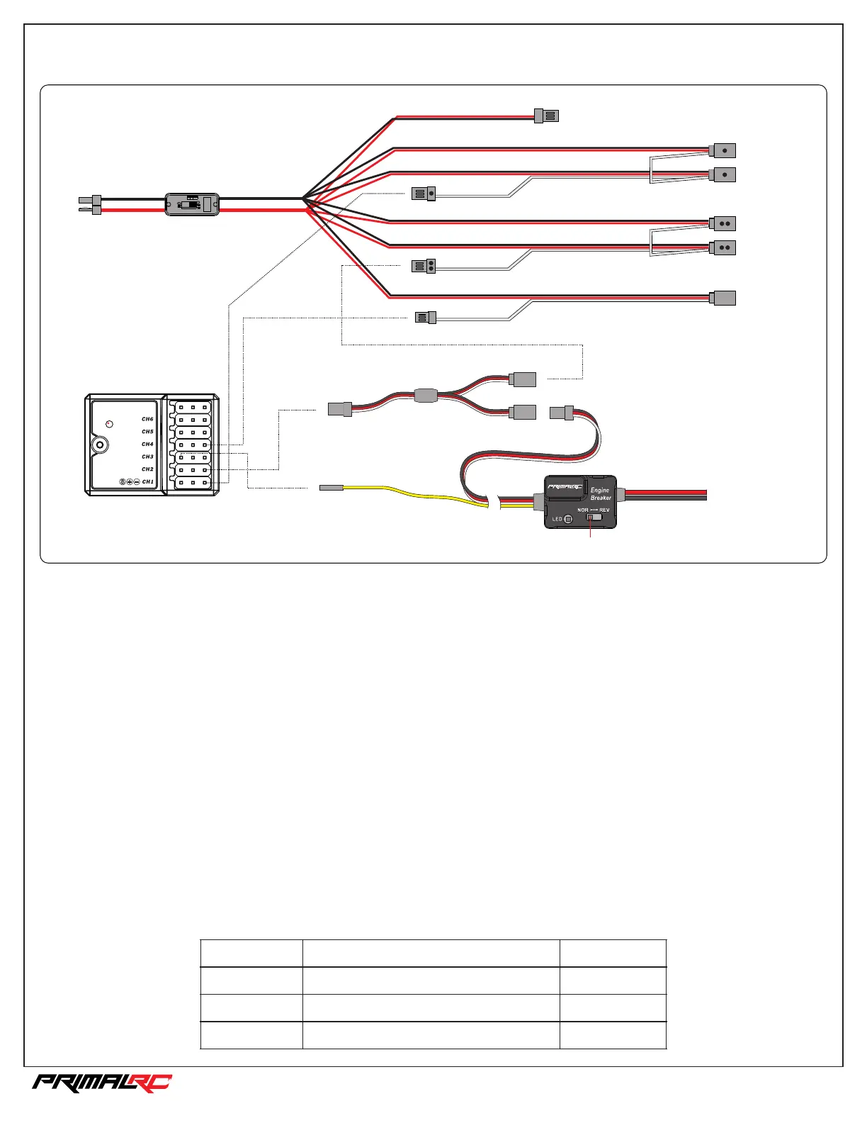
Wiring Diagram
_
+
S
_
+
S
_
+
S
_
+
S
_
+
S
_
+
S
_
+
S
_
+
S
S
+
-
CH1
CH1
CH2
CH4
CH4
Switch
T plug
To battery
To receiver CH1
To Y-link
To receiver CH4
To receiver BATT.
When using extra battery for the receiver,
pull out the positive pin (Red).
VCC
Steering servo 1
Steering servo 2
Throttle servo
Brake servo
Reverse servo
Receiver
_
+
S
_
+
S
_
+
S
CH2
Y-link
To Engine Switch
CH3
S
Reverse switch
Bind/VCC
REMOTE ENGINE KILL-SWITCH & FAIL SAFE
Features
Setup
1. If receiver loses signal, the RED LED will light and engine will cut off. The fail safe will also engage the brakes to stop the vehicle.
2. The engine can manually be cut off by CH3(AUX) from the transmitter. The RED LED will flash.
3. If low battery voltage is detected the RED LED will light and engine will cut off.
LED
DESCRIPTION
Engine status
System Ready
Can start
Cut-off
Cut-off
Low Battery Voltage or no signal
CH3(AUX) is on
DON'T start the engine yet!
Hold the throttle trigger fully to the brake position and set the brake end point adjustment (EPA) to 100%. The RED LED should light signaling
an engine cut-off. If the LED doesn't light, toggle the REVERSE SWITCH and try again. As you setup the receiver's Fail-Saf function, push the
throttle trigger to full brake. Once the Fail-Safe function is setup, return the EPA to its original setting. To verify the Fail-Safe function has been
correctly set, turn off the transmitter. The RED LED should turn on.
If everything is setup and connected correctly the GREEN LED will light up and you're ready start the engine.
The engine can be manually cut-off at any time by pressing the CH3(AUX) button. The RED LED will blink red when successful.
LED Status Display
Green
Red
Red Blinking
1/5th RAMINATOR MONSTER TRUCK