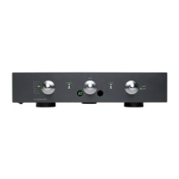
R35 Phono Preamplifier User Guide10
These instructions help you get the best possible sound
from your R35.
Phase
The phase of the AC supply can make a significant
difference to the sound.
Use the Polarity Pen supplied with the R35 to verify which
pin is live on your AC power cable.
Ensure that the live pin of the AC power cable is
connected to the left-hand pin of the power connector,
viewed from the back panel:
Burn-in
Your Primare will start to sound best after an initial burn-in
of approximately 24 hours.
You will notice a further smaller improvement in sound
quality for at least another 3 days’ playing.
Trigger
For convenience the R35 can be powered on and off via
a remote link cable, avoiding the need to switch it on or
off separately from the preamplifier in the system.
To power the R35 on and off remotely from a Primare
processor or preamplifier connect the TRIG OUT signal
from the processor/preamplifier to the TRIG IN socket on
the R35, using a twin core cable terminated in 3.5mm
jack plugs.
The TRIG OUT socket can be used to daisy-chain the
remote output to further Primare products.
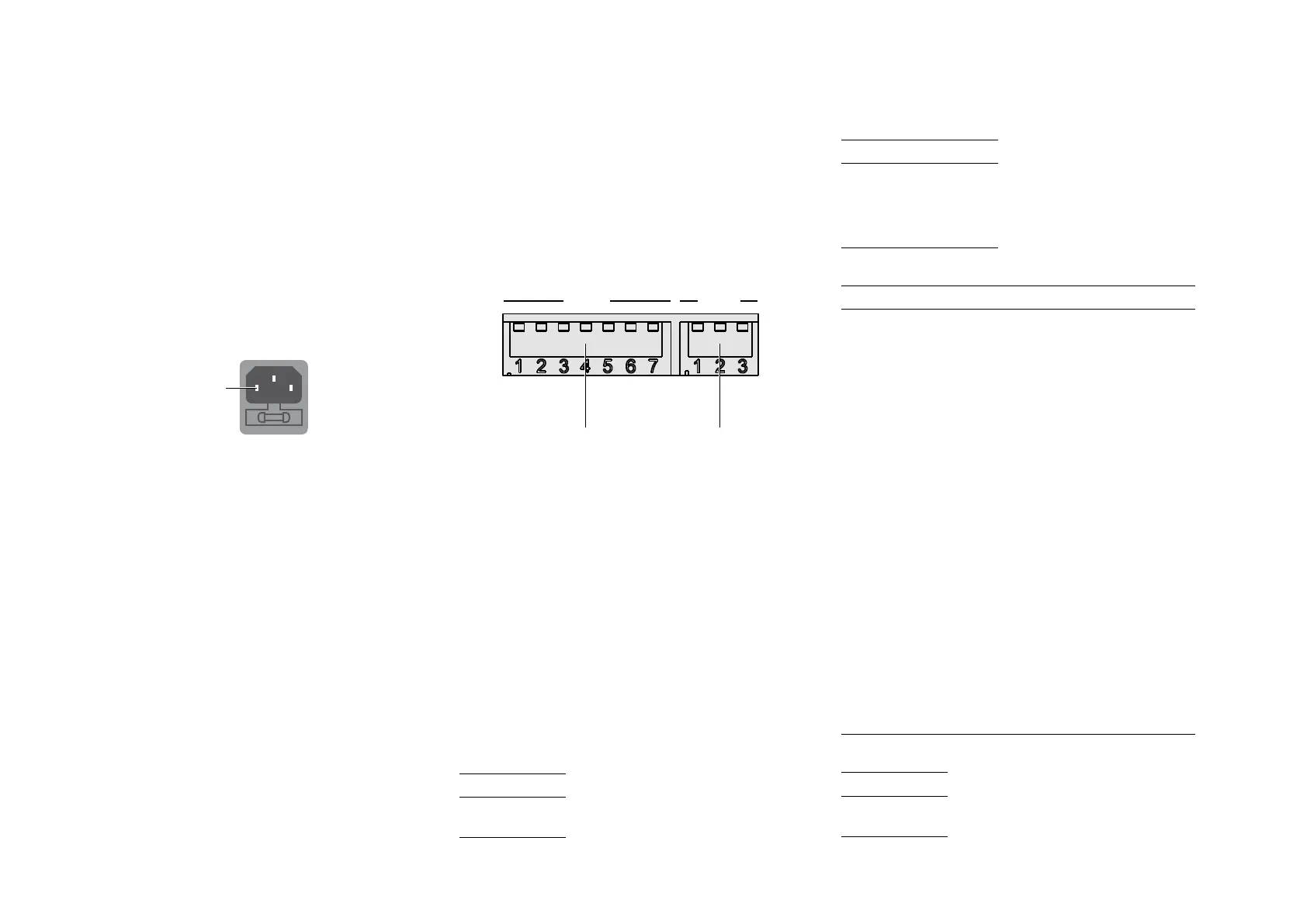
Setting the impedance and capacitance
By default the R35 is configured for an input impedance
of 47k
Ω (MC input) or 2.5kΩ (MM setting), and an input
capacitance of 1nF (MC setting) or 100pF (MM setting),
but you can adjust this using the DIP switches under the
plates on the back panel.
Remove both plates by unscrewing the retaining thumb
screws.
MC
ON
MM
1 2 3 4 5 6 7
8 9 10
Moving magnet
settings
Moving coil
settings
Set the switches up (OFF) or down (ON) according to
the following tables.
You only need to set the switches appropriate to the type
of cartridge you are using.
There are two sets of switches, one for the L channel and
one for the R channel. Set the L and R switches to the
same positions.
Choosing the correct settings
Details of the correct settings will be provided in the
documentation for the cartridge you are using. We
suggest listening to values either side of the recommended
ones to choose the ideal settings for your system.
MM impedance
Switch 8
47k
Ω OFF
2.5k
Ω ON
l
l
ADDITIONAL INFORMATION
MM capacitance
Switch 9 10
100pF OFF OFF
200pF
OFF ON
300pF ON OFF
400pF
ON ON
MC impedance
Switch 1 2 3 4 5 6
10Ω ON ON ON ON ON ON
15Ω ON OFF ON ON OFF ON
18
Ω OFF OFF ON OFF OFF ON
20
Ω OFF OFF OFF OFF OFF ON
25
Ω ON ON ON ON ON OFF
30Ω ON ON OFF ON ON OFF
40
Ω ON OFF ON OFF ON OFF
50Ω OFF OFF OFF OFF ON OFF
60Ω ON ON ON ON OFF OFF
70Ω OFF OFF ON ON OFF OFF
80
Ω ON ON OFF ON OFF OFF
90Ω ON OFF OFF ON OFF OFF
100Ω OFF OFF OFF ON OFF OFF
150Ω ON ON ON OFF OFF OFF
180
Ω OFF ON ON OFF OFF OFF
200
Ω ON OFF ON OFF OFF OFF
250
Ω OFF OFF ON OFF OFF OFF
400
Ω ON ON OFF OFF OFF OFF
600Ω OFF ON OFF OFF OFF OFF
1kΩ ON OFF OFF OFF OFF OFF
47k
Ω OFF OFF OFF OFF OFF OFF
MC capacitance
Switch 7
100pF OFF
1nF ON
 Loading...