EasyManuals Logo

Pro-face GP-4401T User Manual

Pro-face GP-4401T
241 pages
To Next Page IconTo Next Page
To Previous Page IconTo Previous Page
Page #133 background imageLoading...
Page #133 background image
GP4000 Series Hardware Manual
133
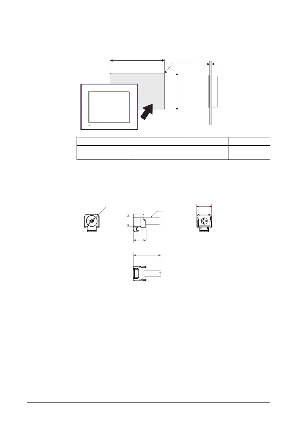
Panel Cut Dimensions
Create a panel cut and insert the GP unit into the opening from the front.
NOTE: Before designing the panel cut, refer to Installation (see page 136).
Installation Fastener Dimensions
ABCR
301.5 mm (+1, -0 mm)
(11.87 [+0.04, -0 in.])
227.5 mm (+1, -0 mm)
(8.96 in. [+0.04, -0 in.])
1.6...5 mm
(0.06...0.2 in.)
3 mm (0.12 in.)
maximum
A
C
R
B
12
0.47
12
0.47
14
0.55
M6
26
1.02
mm
in.
Ø10
Ø0.39

Table of Contents

Other manuals for Pro-face GP-4401T

Questions and Answers:

Question and Answer IconNeed help?

Do you have a question about the Pro-face GP-4401T and is the answer not in the manual?

Pro-face GP-4401T Specifications

General IconGeneral
BrandPro-face
ModelGP-4401T
CategoryTouch Panel
LanguageEnglish

Related product manuals