10
4
77
59
45
95
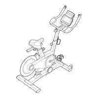
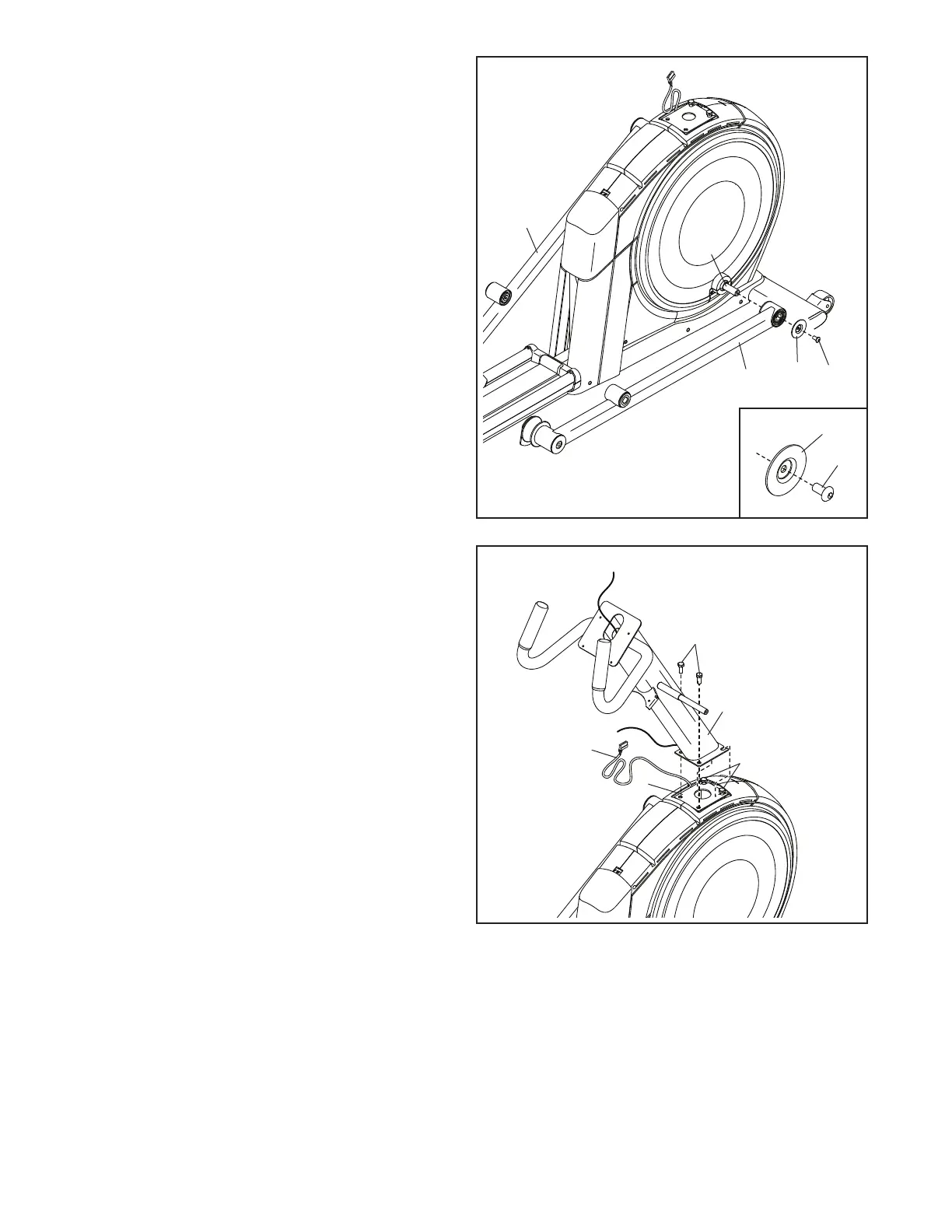
4. Identify the Right Roller Arm (59), orient it as
shown, and slide it onto the right Crank Arm (20).
Attach the Right Roller Arm (59) with
an M8 x 20mm Screw (95) and a Crank
Cover (77); make sure that the Crank Cover is
oriented as shown in the inset drawing.
Repeat this step for the Left Roller Arm (45).
20
95
77
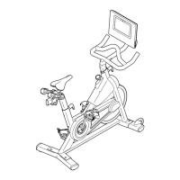
5. Tip: Avoid pinching the Upper Wire (110).
Have a second person hold the Upright (4) on
the Frame (1).
Tip: Two M10 x 25mm Screws (92) are
preattached to the Frame (1).
Attach the Upright (4) with two additional
M10 x 25mm Screws (92); do not fully tighten
the Screws yet.
5
Avoid pinching the
Upper Wire (110)
4
1
92
92
110
 Loading...