10
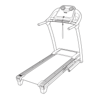
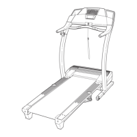
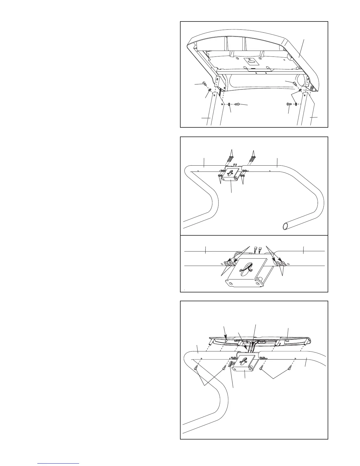
9. Set the Left Handrail (69) and the Right Handrail
(71) on a level surface.
Attach the Handrails (69, 71) to the Handrail
Bracket (70) with four 1/4" x 1 1/2" Bolts (3) and
four 1/4" Nuts (4). See the lower drawing.
Make sure that the Nuts sit inside the indi-
cated square holes in the Handrails. Start all
four Bolts, and then firmly tighten them.
9
3
3
4
4
4
4
69
70
71
5
5
78
77
2
2
2
5
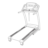
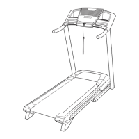
8. Insert the wires into the Right Upright (78). Set
the brackets on the console assembly into the
Right Upright and the Left Upright (77). Be care-
f
ul not to pinch any wires.
A
ttach the console assembly with four 5/16" x
3/4" Screws (2) and four 5/16" Star Washers
(5). Start all four Screws, and then firmly
tighten them.
Console
A
ssembly
8
7
71
69
86
7
10. Hold the Pulse Assembly (72) near the Handrail
Bracket (70). Orient the Pulse Assembly so
that the indicated plastic boss will fit into the
hole in the Right Handrail (71). Make sure that
the two Pulse Ground Wires (86) are extending
from the top of the Handrail Bracket. Connect
the two Pulse Ground Wires to the ground wires
on the Pulse Assembly.
Next, insert the wire harness on the Pulse
Assembly (72) into the top of the Handrail
Bracket (70) and pull it out of the side as shown.
Set the Pulse Assembly (72) on the Handrails
(69, 71). Insert the excess ground wire into the
Handrails. Attach the Pulse Assembly with four
#8 x 3/4" Screws (7). Be careful not to over-
tighten the Screws. Be careful not to pinch
any wires.
Boss
72
Square Holes
10
2
69
71
70
Pulse Wires
Wire Harness