For technical questions call: 1-800-665-8685
8319683 / 8319709
V 1.35
8
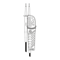
PHASE ROTATION TEST
Left LED and right LED for phase rotation test may operate on various
wiring systems, but effective testing results can be obtained only on three-
phase, 4-wire systems.
1. Grasp the instrument firmly
and connect both probes to
the object under test (grasp
method shown below).
2. Phase-to-phase voltage is
indicated by each voltage
LED.
3. Right LED indicates that the
field is rotating towards the
right direction of the probe
- with this connection, the
motor will go in a positive
rotation.
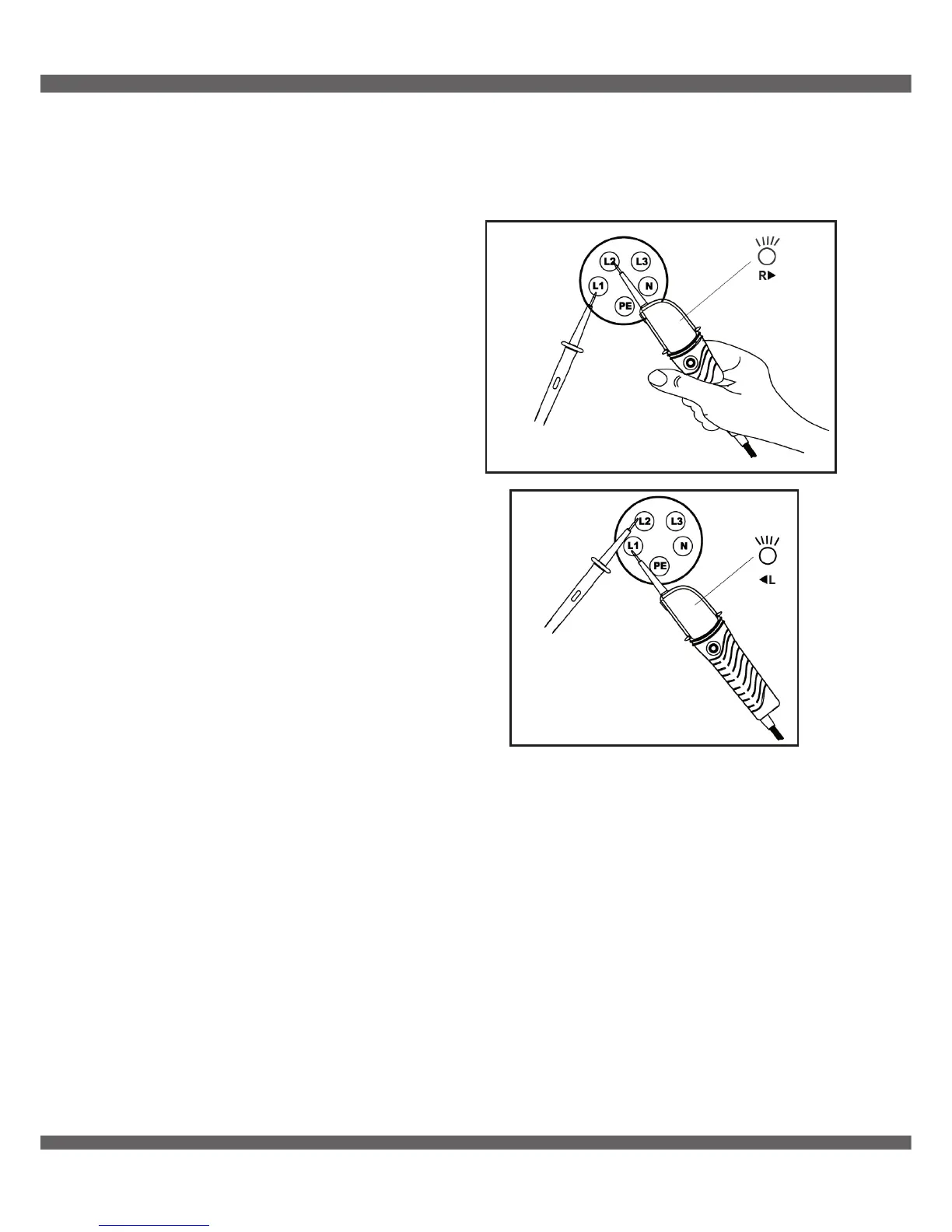
4. Left LED indicates that the
field is rotating towards the
left direction of the probe
- with this connection, the
motor will go in a negative
rotation.
THE PRINCIPLE OF MEASUREMENT
The instrument detects the phase rising order regarding the user as EARTH.
NOTE:
Function of this test may not be fully achieved if the insulation
condition of user or of the equipment under test is not enough.
Fig. 4
Fig. 5