Compound Slope Setup
2. Using the compound slope chart supplied with the S2 kit, find the two
slopes for the site on the chart and follow their row and column until they
intersect. Remember that the main slope is the steeper of the two slopes.
The upper number in the box where the two slopes intersect is the angle to
set into the S2 adapter. The lower number is the resultant slope to dial into
the laser's slope counter. Note: The slope number is displayed with greater
precision than the slope counter increments.
3. Rotate the S2 adapter until it matches the angle determined with the slope
chart. Note: if, when standing behind the laser, the highest corner on the
site is to the right of the grade sight, you must rotate the adapter counter
clock-wise until you reach the proper reading. If the high corner is to the left,
you must rotate the adapter clock wise.
4. Turn the entire laser toward the uphill direction of the cross slope (toward
the highest corner on the site) until the slope alignment sight is once again
aligned parallel to the main slope. The laser is now at the proper angle.
5. To finish the setup, dial in the resultant slope determined from the chart
and go to work. Note: you can re-check the setup at any time by doing the
following: A. Verify the slope counter setting. B. Verify that the proper angle
is set into the compound slope adapter. C. Verify that the slope sighting slot
is parallel with the main slope direction. D. Verify that the uphill direction of
the laser is aimed toward the high corner of the site.
Always set at least two grade checking stakes that are 90 degrees apart so
that you can verify the laser setup from day to day on the site.
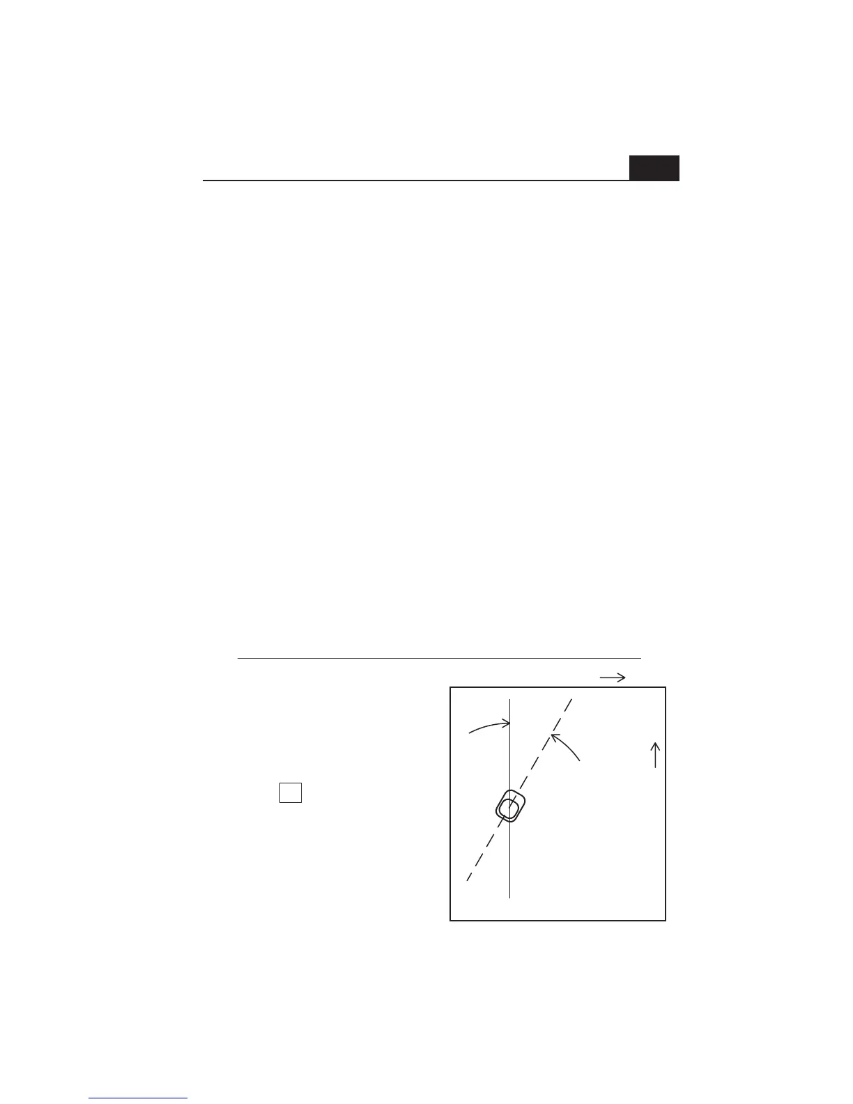
Low corner
High corner
Main slope= .25% up
Compound slope example
31°
Resultant
slope .29%
1. Zero the compound slope adapter ring and
aim the laser parallel to the main slope, with
the up-slope direction of the laser aimed
up-hill on the site.
2. Look-up the intersection of the main slope
(.25) and the cross slope (.15) using the
slope chart. The box at the intersection.
looks like this:
3. Turn the adapter sighting slot 31° counter
clock-wise.
4. Turn the entire laser to re-align the sighting
slot parallel with the main slope. (the laser is
now aimed 31° toward the high corner).
5. Dial the resultant slope of .29% into the
slope counter. Setup is complete.
Cross slope= .15% up
31
0.292
11