30
Graphic Display - 2 -
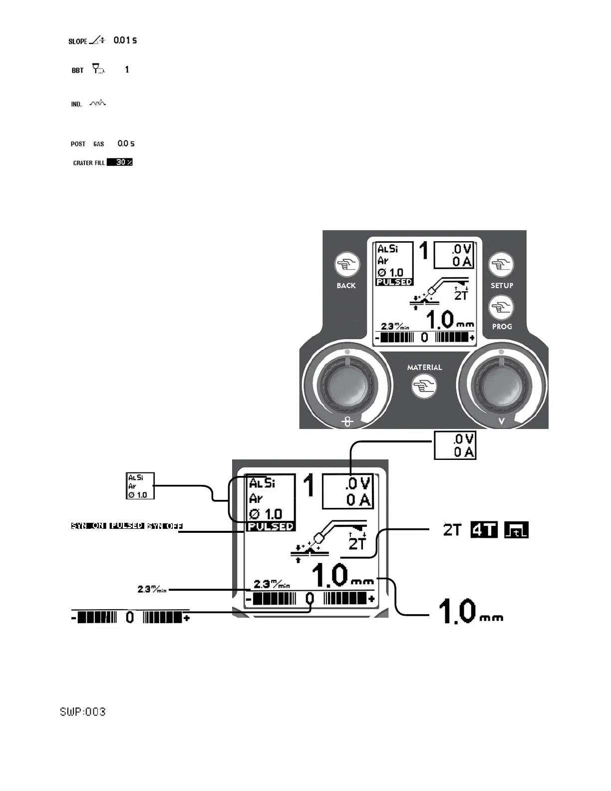
Note: based on the set welding mode, some data on the MIG/MAG screen can not be visualized.
• Synergic Program Information
• MIG/MAG MODE:
PULSED, SYN ON, SYN OFF
• Wire Speed
• Regulation Scale:
Manual-electronic inductance
SYN / PULSED- balance
• Digital Ammeter/Voltmeter
• Working Modes:
2Stroke
4Stroke
• Pointer:
Manual - voltage
SYN/PULSED - Thickness
SYNERGIC WORKING POINT
The Synergic Program indicates the effective working program inside the selected synergic curve (Gas,
Diameter, Material).
Figure 11
Once selected a Synergic Curve, Slope, BBT and Inductance settings go back to their default values.
Tasto PROG
- 4 -
Salva e richiama i punti personalizzabili dall’o-
peratore.
Tasto MATERIAL
- 6.2 -
6.1 Mig/Mag Manuale (sinergia OFF)
Regola il valore dell’induttanza elettronica
6.2 Mig/-------------Mag Sinergica/
Sinergica Pulsata
Dà accesso alla schermata per la scelta del programma
sinergico
Figura 10
3
5
6
7
2
1
4
Slope: regulation of the time the wire needs from the striking speed to the welding
speed (0-1.50 sec)
BBT: regulation of the lenght of the wire protruding from the torch at the end of welding
(1-10)
IND.: regulation of the electronic inductance value (0-11)
Low Value = more spatters
High Value = less spatters
POST GAS: Regulation of the gas outflow time at the end of welding (0 – 5 Sec.)
Percentage of reduction of the welding parameter during the crater Filler (30 - 100%)
(only 4T)
Duration of the Welding Current Slope Down changes according to the set crater filler
percentage.
11