28
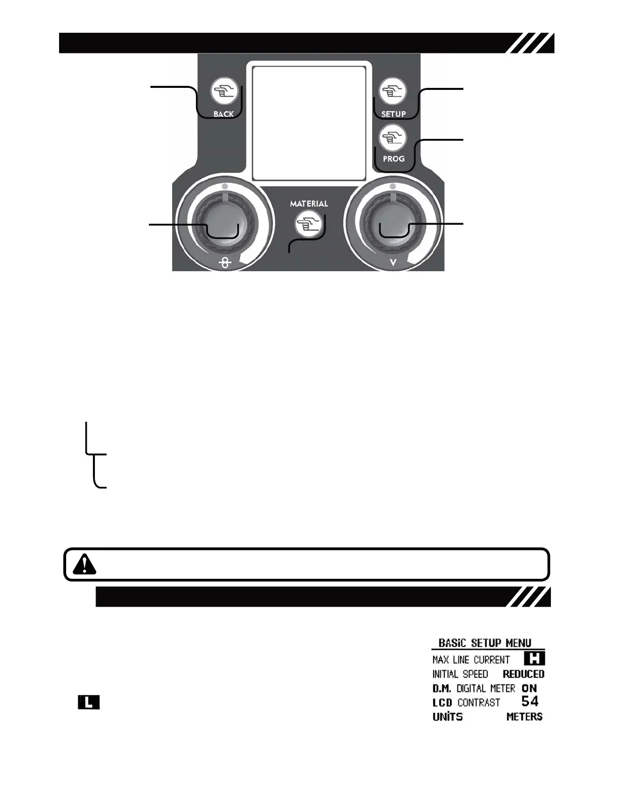
CONTROL INTERFACE
SETUP Key allows to run through the menus by selecting in sequence the modifiable parameters.
The right knob changes the size value previously selected with the SETUP Key.
Graphic Display
Mode Key
• return to the main screen after parameters setting
1
3
1
2
Setup Key
setting of the secondary parameters in all welding processes
Synergy: OFF /ON/PULSED, 2Stroke/4Stroke/Spot welding, Spot Time, Motor Slope, BBT, Electronic Inductance,
Post Gas, Crater Filler
3
4
Prog save & recall Key
saves and recalls the functioning points that may be changed by the operator
4
5
5
6
7
Right Regulation Knob ( Volts / Amps)
Main Regulation Knob
Material Key
submenus selection key
6
6.1 Manual Mig/Mag (synergy OFF)
Adjustment of the electronic inductance value
6.2 Synergic Mig/Mag/ Synergic Pulsed
Screen access for the synergic program selection
7
Left Regulation Knob
• Wire speed ( Mig )
• Balance (Synergic and pulsed Mig)
2
Figure 6
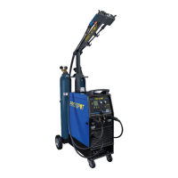
BASIC SETUP MENU
To enter the Basic Setup Menu power the unit on; while the display views the unit logo, press the Setup
Key - 3 -. Use the Right Regulation Knob - 5 - to adjust the modifiable parameters:
MAX LINE CURRENT - L/H
Setting of the maximum current that the unit may absorb by the input power
supply according to the branch circuit capability. In order to utilize the maximum
output capability of the unit, a branch circuit capable of 32 amps in required.
Note: if L (low) is set, the absorbed current will be automatically reduced.
The letter will appear on the unit main screen if selected.
INITIAL SPEED - reduced/normal
Reduced Initial Speed setting reduces the speed of the wire feeding on the workpiece to optimize the striking.
Figure 7
9