HearthSense
200549-05A16
INSTALLATION
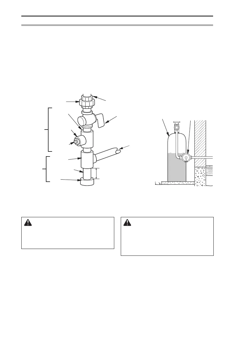
external regulator with the vent pointing down
as shown in Figure 17. Pointing the vent down
protects it from freezing rain or sleet.
Install sediment trap in supply line as shown
in Figure 16. Place sediment trap where it is
within reach for cleaning. Place sediment trap
where trapped matter is not likely to freeze. A
sediment trap traps moisture and contaminants.
This keeps them from going into heater controls.
If sediment trap is not installed or is installed
wrong, heater may not run properly.
Figure 16 - Gas Connection
* Purchase the optional CSA design-certied equipment
shuto valve from your dealer.
For propane installations, apply pipe joint
sealant lightly to male threads. This will
prevent excess sealant from going into pipe.
Excess sealant in pipe could result in clogged
heater valves.
The installer must supply an external regulator.
The external regulator will reduce incoming
gas pressure. You must reduce incoming gas
pressure to between 11" and 14" of water. If
you do not reduce incoming gas pressure,
heater regulator damage could occur. Install
Figure 17 - External Regulator
with Vent Pointing Down
External
Regulator with
Vent Pointing
Down
Propane
Supply Tank
Equipment
Shuto Valve
Ground
Joint Union
3/8" NPT
Pipe Nipple
Tee Joint
Reducer
Bushing to
1/8" NPT
1/8" NPT
Plug Tap
Test Gauge
Connection*
Sediment
Trap
Tee Joint
Pipe Nipple
Gap
3" Minimum
Natural Gas
From Gas Meter
(5" W.C.** to 9.5" W.C.
Pressure)
Propane
From External
Regulator (11"
W.C.** to 14" W.C.
Pressure)
CHECKING GAS CONNECTIONS
1. Disconnect heater with its appliance main
gas valve (control valve) and equipment
shuto valve from gas supply piping sys-
tem. Pressures in excess of 1/2 PSIG will
damage heater regulator.
2. Cap o open end of gas pipe where equip-
ment shuto valve was connected.
3. Pressurize supply piping system by either
opening propane supply tank valve for
propane gas or opening main gas valve
WARNING: Test all gas piping
and connections for leaks after
installing or servicing. Correct
all leaks at once.
WARNING: Never use an open
ame to check for a leak. Apply a
noncorrosive leak detection uid
to all joints. If bubbles form, there
is a leak. Correct all leaks at once.
PRESSURE TESTING GAS SUPPLY PIPING SYSTEM
Test Pressures In Excess Of 1/2 PSIG (3.5 kPa)
located on or near gas meter for natural
gas or using compressed air.
4. Check all joints of gas supply piping sys-
tem. Apply a noncorrosive leak detection
uid to all joints. If bubbles form, there may
be a leak.
5. Correct all leaks at once.
6. Reconnect heater and equipment shuto
valve to gas supply. Check reconnected
ttings for leaks.