INSTALLATION
CHECKING GAS CONNECTIONS
WARNING: Test all gas piping
and connections for leaks after
installing or servicing. Correct
all leaks at once.
WARNING: Never use an open
ame to check for a leak. Apply
a noncorrosive leak detection
uid to all joints. If bubbles form,
there is a leak. Correct all leaks
at once.
PRESSURE TESTING GAS SUPPLY
PIPING SYSTEM
Test Pressures In Excess Of 1/2 PSIG
(3.5 kPa)
1. Disconnect heater with its appliance main
gas valve (control valve) and equipment
shutoff valve from gas supply piping sys-
tem. Pressures in excess of 1/2 PSIG will
damage heater regulator.
2. Cap off open end of gas pipe where equip-
ment shutoff valve was connected.
3. Pressurize supply piping system by either
opening propane/LP supply tank valve or
using compressed air.
4. Check all joints of gas supply piping sys-
tem. Apply a noncorrosive leak detection
uid to all joints. If bubbles form, there may
be a leak.
5. Correct all leaks at once.
6. Reconnect heater and equipment shutoff
valve to gas supply. Check reconnected
ttings for leaks.
Test Pressures Equal To or Less Than
1/2 PSIG (3.5 kPa)
1.
Close equipment shutoff valve (see Fig-
ure 15).
2. Pressurize supply piping system by either
opening propane/LP supply tank valve or
using compressed air.
3. Check all joints from propane/LP tank to
equipment shutoff valve (see Figure 16).
Apply a noncorrosive leak detection uid
to all joints. If bubbles form, there is a leak.
4. Correct all leaks at once.
as shown in Figure 14, page 14. Pointing
the vent down protects it from freezing rain
or sleet.
Install sediment trap in supply line as shown
in Figure 13, page 14. Place sediment trap
where it is within reach for cleaning. Place
sediment trap where trapped matter is not
likely to freeze. A sediment trap traps mois-
ture and contaminants. This keeps them from
going into heater controls. If sediment trap is
not installed or is installed wrong, heater may
not run properly.
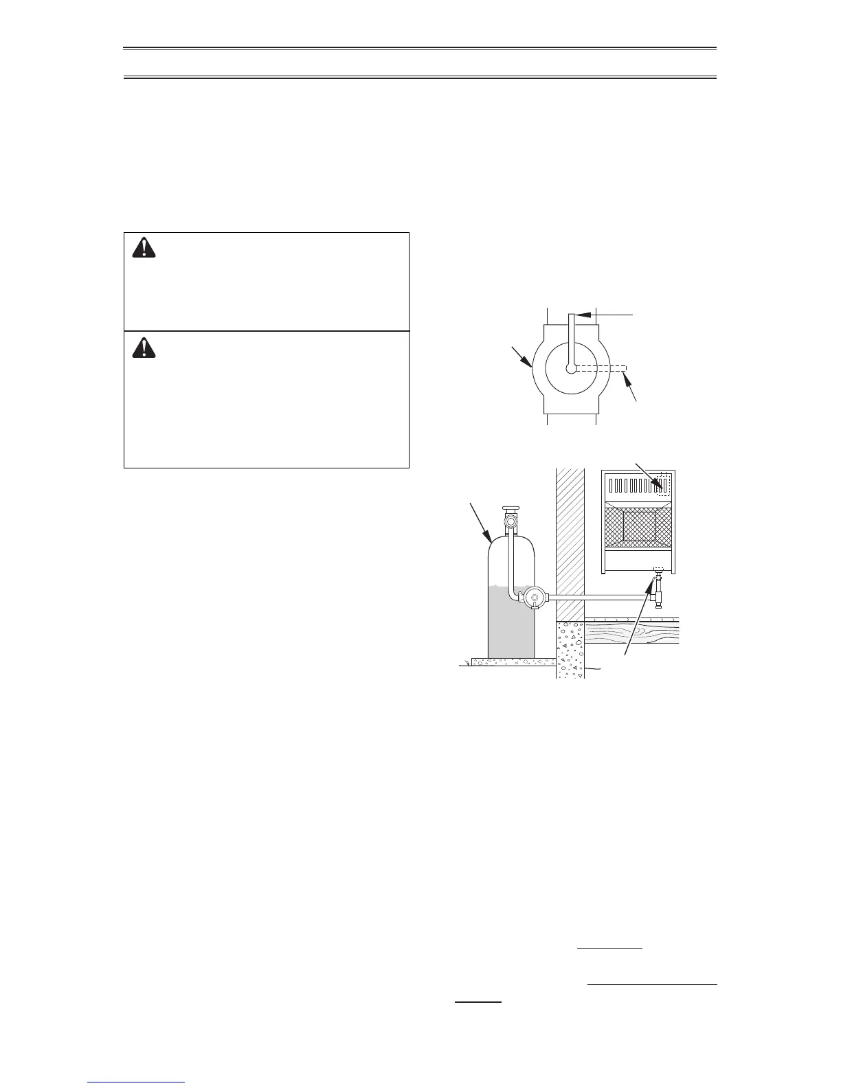
Figure 15 - Equipment Shutoff Valve
Open
Closed
Equipment
Shutoff Valve
Figure 16 - Propane/LP Fuel Supply
Propane/LP
Supply Tank
Gas Valve
Equipment
Shutoff Valve
PRESSURE TESTING HEATER GAS
CONNECTIONS
1.
Open equipment shutoff valve (see Fig-
ure 15).
2. Open propane/LP supply tank valve.
3. Make sure control knob of heater is in the
OFF position.
4. Check all joints from equipment shutoff
valve to control valve (see Figure 16).
Apply a noncorrosive leak detection uid to
all joints.
Bubbles forming show a leak.
5. Correct all leaks at once.
6. Light heater (see Operation, page 16).
Check all other internal joints for leaks.
7. Turn off heater (see To Turn Off Gas Ap-
pliance, page 18).
8. Replace lower front panel.