Do you have a question about the Prodigit 3354F and is the answer not in the manual?
Covers general, environmental, power application, grounding, fuse, and explosive atmosphere safety aspects.
Describes the 3350F Series Electronic Load's purpose, operation modes, and control interfaces.
Highlights the key capabilities and functionalities of the 3350F Series Electronic Load.
Lists the standard accessories provided and available optional interface modules.
Details the electrical and physical specifications, including AC input, power, dimensions, and weight.
Covers initial inspection, checking line voltage, and setting the appropriate voltage for operation.
Details grounding requirements, adjusting feet for stability, and rack mounting guidelines.
Specifies operating environment and lists important electrical safety symbols.
Instructions for cleaning the unit and the steps for powering it up correctly.
Describes the procedure for connecting wires to the load input terminal on the rear panel.
Details connecting the unit via RS-232C interface to a computer.
Explains how to connect the 3350F mainframe using a USB interface.
Provides instructions for connecting the unit via the LAN interface.
Describes the simultaneous use of GPIB and RS-232 interfaces and their limitations.
Explains how to use analog signals for programming load current in CC and CP modes.
Details how to set rise and fall slew rates for controlled current transitions.
Describes the emergency stop input and alarm output signals for safety.
Explains how load wire inductance can affect operation and cause voltage drops.
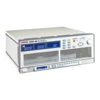
Identifies and explains the components and controls on the front panel of the 3350F.
Indicates the model number and specifications displayed on the unit.
Explains the NG indicator, and the four operating modes: CC, CR, CV, CP.
Describes the REMOTE LCD indicator and how to switch between remote and local control.
Explains the functions of the left and middle LCDs in normal and test modes.
Details how the right display shows preset values and limit settings in different modes.
Explains how the right display shows dynamic waveform parameters like time and slew rate.
Describes how to configure sense, load ON/OFF voltages, and polarity.
Details the setup parameters for Short, Over Power, and Over Current Protection tests.
Explains the indicators for the four operating modes.
Details the function of the LOAD key for ON/OFF and the DYN key for dynamic operation.
Explains the RANGE key for setting resolution and forcing range II.
Describes using the LEVEL key to set high and low load values for static and dynamic modes.
Explains how the PRESET key accesses modes for setting current, resistance, voltage, or power.
Details how the LIMIT key sets upper/lower thresholds for voltage, current, and power.
Explains how the NG indicator works based on voltage limits in CC mode.
Describes NG indicator behavior for dynamic, Constant Resistance, and Constant Voltage modes.
Explains how to set high/low current levels, rise/fall times, and time high/low.
Details using the CONFIG key to set sense function, automatic load ON/OFF, and polarity.
Explains how to enter and configure parameters for a SHORT circuit test.
Details setting up Over Current Protection tests, including start, step, stop current, and voltage threshold.
Explains setting up Over Power Protection tests, including start, step, stop power, and voltage threshold.
Describes the use of the START/STOP key for initiating and halting tests.
Explains how to use the rotary knob and associated keys for value adjustment and navigation.
Details the positive and negative power input terminals and connection considerations.
Explains the V-sense terminals for compensating voltage drops in load lines.
Describes the I-monitor terminal for measuring input current or short current.
Explains the REMOTE indicator and indicators for GPIB, RS232, and USB interfaces.
Describes the main display, memory bank, and state indicators.
Details the EXIT, TEST, ENTER, EDIT buttons for auto-sequence setup.
Explains numbered memory buttons, LOCAL, STORE, LOAD, and INIT buttons.
Instructions for setting the GPIB address using the system button.
Steps to set the RS232 baud rate using the system button.
Explains how to enable or disable the buzzer for signaling test status.
Details the procedure for saving and loading instrument configurations and settings.
Describes how to use the wake-up function to recall settings at power-on.
Explains how to create and edit auto-sequences, including setting steps and timing.
Describes how to run auto-sequences, interpret PASS/FAIL results, and handle NG status.
Lists the default initial settings for the 3350F and 3351F load modules.
Lists the default initial settings for the 3352F and 3353F load modules.
Lists the default initial settings for the 3354F and 3356F load modules.
Discusses five connection methods and recommendations for wire gauge and voltage drop.
Explains how to use the knob for course and fine adjustment of load current in different modes.
Details the protection circuits for over voltage, over current, over power, and over temperature.
Explains the protection against incorrect DC source polarity and how it's indicated.
Overview of using a PC for remote control of the 3350F Electronic Load.
Summarizes RS-232 protocol parameters like baud rate, parity, and data bits.
Lists commands for setting and querying parameters like slew rates, load ON/OFF voltages.
Provides a summary of commands for setting upper and lower limits for current, power, and voltage.
Lists commands for controlling load status, mode, preset, sense, level, and dynamic settings.
Lists system commands for recall, store, remote, local, and naming.
Lists commands for measuring current, voltage, and power.
Details commands for setting up, saving, repeating, and running auto-sequences.
Lists complex format commands for setting preset values, slew rates, and test configurations.
Lists commands for querying preset values, TCONFIG, OCP, OPP, and STIME.
Details limit commands for current, power, voltage, and short current thresholds.
Lists stage commands for load status, mode, short test, preset, sense, level, dynamic, error, NG, and protection.
Lists system commands for recall, store, remote, local, and naming.
Describes querying protection status and clearing error registers.
Details commands for range setting, GO/NG enable, polarity display, and test start/stop.
Details commands for recalling and storing the instrument's status and configuration.
Explains commands for controlling remote status and reading the model number.
Details the NAME command to read the model number of the load.
Explains commands for controlling RS232 remote status and finishing RS232 communication.
Details the command to read the actual current loading of the unit.
Describes commands to read the voltage and power loading of the unit.
Illustrates a typical setup for local sensing with the load connected to a DC power supply.
Shows a setup for remote sensing, connecting Vsense cables to the power supply output.
Details CC mode use for load regulation, cross regulation, and battery discharge characteristics.
Explains static and dynamic operation in CC mode, including switchable current levels.
Instructions for setting high and low current levels using the LEVEL key in CC mode.
Explains CV mode use for checking current sources, battery chargers, and power supply current limits.
Describes how to record current curves by setting CV voltage for load regulation testing.
Instructions for setting high and low voltage levels using the LEVEL key in CV mode.
Details CR mode use for testing power supplies, providing a 'soft start' feature.
Instructions for setting high and low resistance values using the LEVEL key in CR mode.
Explains CP mode use for battery testing, measuring energy capacity, and simulating loads.
Instructions for setting high and low power values using the LEVEL key in CP mode.
Describes using the load as a high current constant current source for battery charging or parallel operation.
Explains connecting the load in series for zero-volt condition testing, suitable for low voltage battery cells.
Details the rule for connecting multiple output power supplies to 3350F series loads in parallel.
Step-by-step guide for performing an Over Current Protection test manually.
Lists commands for setting up and executing OCP tests remotely.
Step-by-step guide for performing an Over Power Protection test manually.
Lists commands for setting up and executing OPP tests remotely.
Step-by-step guide for performing a SHORT circuit test manually.
Lists commands for setting up and executing SHORT tests remotely.
Instructions for installing the USB driver for the PL-2303 USB-to-Serial converter.
Guides connecting to the network and setting up IP address and subnet mask.
Explains how to set modes, ranges, levels, and store settings for auto-sequences.
Describes how to run auto-sequences, interpret PASS/FAIL results, and handle NG status.
| Brand | Prodigit |
|---|---|
| Model | 3354F |
| Category | Power Supply |
| Language | English |