Do you have a question about the Prodigit 3350F Series and is the answer not in the manual?
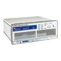
Provides an overview of the 3350F Series Electronic Load and its capabilities.
Instructions for checking the instrument upon arrival and after transport.
Procedure for verifying and setting the correct input line voltage for operation.
Steps for safely replacing the power fuse in the instrument.
Essential information on grounding the instrument to prevent electric shock hazards.
Guidance on adjusting the instrument's feet for optimal viewing angle.
Information on mounting the instrument in a standard 19-inch rack.
Specifies the suitable operating environment for the instrument.
Explains important electrical symbols used in the manual and on the device.
Instructions for cleaning the instrument safely and effectively.
Steps for powering up the instrument, including pre-operation checks.
Describes how to connect the load input terminals on the rear panel.
Guidance on what to do if the instrument is damaged or requires repair.
Details on connecting the instrument via GPIB for remote control.
Instructions for connecting the instrument using the RS-232C interface.
Information on connecting the instrument via USB.
Guide for connecting the instrument using the LAN interface.
Describes limitations and usage of combined GPIB and RS232 interfaces.
Explains the use of the analog programming input terminal.
Details on setting and controlling the load current slew rate.
Explains the emergency stop and alarm signal functions.
Discusses the impact of load wire inductance and how to mitigate it.
Details the components and layout of the instrument's front panel.
General guidelines for operating the electronic load.
Explains various indicators like MODE, NG, and REMOTE on the front panel.
Details the functions of the left, middle, and right 5-digit LCD displays.
Details the function and display of the right 5-digit LCD.
Explains how to set preset values based on the selected operating mode.
Describes how to set upper and lower limits for measurements.
Details how to configure dynamic waveform parameters.
Explains configuration options like SENSE, LDon, LDoff, and POLAR.
Guides on setting parameters for SHORT, OPP, and OCP tests.
Explains MODE selection and indicators for CC, CR, CV, CP.
Details LOAD and DYN keys, their LEDs, and operation.
Explains RANGE and LEVEL keys for setting resolution and values.
Describes Preset key access and mode-specific preset settings.
Details the LIMIT key for setting thresholds and viewing settings.
Explains DYN key for dynamic waveform timings and parameters.
Describes CONFIG key for sense, LDon, LDoff, and POLAR settings.
Guides on using the SHORT key for initiating short circuit tests.
Explains the OCP key for setting up over current protection tests.
Details the OPP key for setting up over power protection tests.
Describes START/STOP key and rotary knob functionality.
Details DC INPUT terminals and V-sense input for voltage compensation.
Describes the I-monitor terminal for current measurement.
Details front panel displays, indicators, and interface card status.
Explains the REMOTE mode and how to switch back to local control.
Indicates the display when the GPIB interface is fitted.
Indicates the display when the RS232 interface is fitted.
Indicates the display when the USB interface is fitted.
Indicates the display when the LAN interface is fitted.
Describes the main display area of the instrument.
Explains the display for memory banks and test time T1.
Details the display for memory states and test time T2.
Describes the function of the arrow buttons for adjusting values.
Describes the function of buttons on the right side of the mainframe.
General instructions for operating the instrument.
Details on setting system parameters like GPIB address and baud rate.
Explains storing/recalling settings and the WAKE-UP function.
Information on creating and running auto-sequences for testing.
Steps for editing auto-sequence programs.
Instructions for executing auto-sequences and interpreting test results.
Lists the factory default initial settings for the load module.
Guidance on selecting and connecting input wires for optimal performance.
Explains how to adjust load current using the course/fine adjustment knob.
Details the various protection features like OVP, OCP, OPP, OTP.
Overview of using the instrument with a PC for remote control.
Details the RS-232 interface parameters and command summary.
Lists remote control commands for settings, abbreviations, and language.
Explains commands for setting and reading preset values like slew rate.
Details commands for setting and reading current, power, and voltage limits.
Commands for setting load status, mode, and test parameters.
Commands for system functions like recall, store, remote, and local control.
Commands to read current, voltage, and power measurements.
Illustrates local sense connections for the electronic load.
Shows a setup using remote sensing for voltage drop compensation.
Explains CC mode for load regulation and battery testing.
Step-by-step guide for operating the instrument in CC mode.
Details CV mode for checking load regulation and current limits.
Step-by-step guide for operating the instrument in CV mode.
Explains CR mode for testing sources and providing a 'soft start'.
Step-by-step guide for operating the instrument in CR mode.
Details CP mode for battery evaluation and simulating loads.
Step-by-step guide for operating the instrument in CP mode.
Describes using the load as a high current constant current source.
Explains an application for testing low voltage battery cells.
Provides rules for connecting multiple electronic loads in parallel.
Instructions for performing Over Current Protection (OCP) testing.
Step-by-step guide for manual OCP testing.
Commands for performing OCP testing via remote control.
Instructions for performing Over Power Protection (OPP) testing.
Step-by-step guide for manual OPP testing.
Commands for performing OPP testing via remote control.
Instructions for performing SHORT circuit testing.
Step-by-step guide for manual SHORT testing.
Commands for performing SHORT testing via remote control.
Provides a C language example program for GPIB control.
Instructions for installing the USB driver for the instrument.
Steps for connecting the instrument to the network via LAN.
Steps for editing auto-sequence programs.
Instructions for executing auto-sequences and interpreting test results.
| Brand | Prodigit |
|---|---|
| Model | 3350F Series |
| Category | Power Supply |
| Language | English |