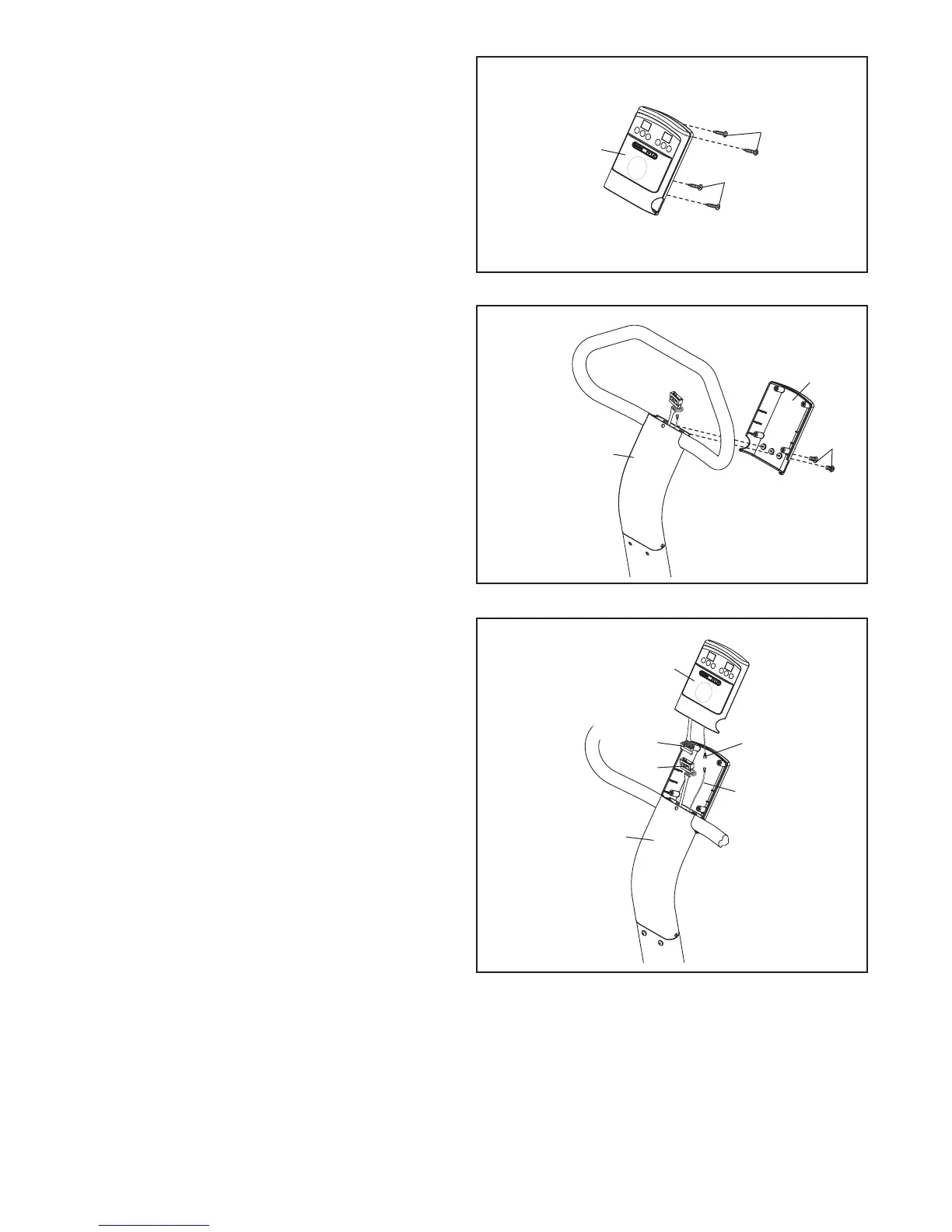
9. Attach the back of the Console (3) to the Upper
Upright (36) with two M4 x 16mm Patch Screws
(26). Do not tighten the Patch Screws yet.
9
36
3
26
10. While a second person holds the front of the
Console (3) near the Upper Upright (36), con-
nect the console ground wire to the Ground
Wire (41). Next, connect the console wire to the
Wire Harness (43). Then, insert the wires into
the Upper Upright.
10
3
41
Console
Ground Wire
36
Console
Wire
43
10
8
. Remove the four M4 x 12mm Self-tapping
Screws (27) from the back of the Console (3).
S
et the Self-tapping Screws aside until step
11.
8
2
7
27
3