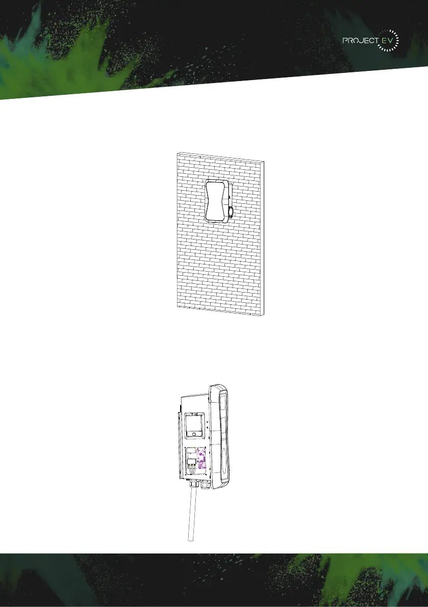
Installation
Wall Mounted
3. Mount the charge point onto the bracket, and fix it with the 2 screws at the bottom of a
charge point. This will secure the charger to the bracket.
4. Remove the side plate, crimp the cables using insulated ferrule’s into terminals
provided. Polarity can be found written on the PCB below the connections. Check the
wiring before powering up - the RCBO is in the top window and may need the reset
indicator resetting by pressing this in before the RCBO can be reset. Once complete, re-fit
the access panel.
3XWWKHFKDUJHSRLQWRQWRWKHEUDFNHWDQGIL[LWZLWKWKHVFUHZVDWWKHERWWRPRI
WKHFKDUJHSRLQW7KHLQVWDOODWLRQLVGRQH
&ULPSWKHEHORZVKRZQLQVXODWHGIHUUXOHRUULQJWHUPLQDOVRQWKHHQGRIWKH$&LQSXW
ZLUHV&RQQHFWWKHZLUHVLQWRWKHWHUPLQDOEORFNRIWKHFKDUJHSRLQWDVEHORZ&KHFNWKH
ZLULQJDQGWKHQFORVHWKH5&'LQWKHVLGHZLQGRZ&ORVHWKHVLGHZLQGRZZLWKWKHFRYHU
WKHQWKHZULQJLVGRQH
0RXQWRQDSROH
2SHQWKHSDFNDJLQJRIWKHSROHWDNHRXWWKHSROHDQGPRXQWLQJDFFHVVRULHV
7KHSROHPXVWEHLQVWDOOHGRQDKDUGVXUIDFHFRQFUHWHVXUIDFHLVUHFRPPHQGHGLW
FDQDOVREHPRXQWHGRQDVROLGJURXQG'ULOOKROHVDFFRUGLQJWRWKHUHTXLUHPHQWVPDUNHG
RQWKHLOOXVWUDWLRQIRUIL[LQJH[SDQVLRQEROWV
)L[WKHSROHRQWRWKHKROHVZLWKH[SDQVLRQEROWV7KHLQSXWFDEOHVVKDOOJRLQWRWKH
SROH IURP WKH ERWWRP PLGGOH DUHD DQG FRPH RXW RI LW IURP WKH DUHD EHORZ WKH FDEOH
KRRNHU
3.1.3 Put the charge point onto the bracket, and x it with the 2 screws at the bottom of
the charge point. The installation is done.
3.1.4 Crimp the insulated ferrule or ring terminals on the end of the AC input wires.
Connect the wires into the terminal block of the charge point as below. Check the
wiring and then close the RCD in the side window. Close the side window with the
cover, then the wiring is completed.
3.2.2 The pole must be installed on a hard surface, concrete surface is recommended,
it can also be mounted on a solid ground. Drill holes according to the requirements
marked on the illustration for xing expansion bolts.
3.2.3 Fix the pole onto the holes with expansion bolts. The input cables shall go
into the pole from the bottom middle area and come out of it from the area below the
cable hooker.
3.2 Mount on a pole
3.2.1 Open the packaging of the pole, take out the pole and mounting accessories.
8 9
3XWWKHFKDUJHSRLQWRQWRWKHEUDFNHWDQGIL[LWZLWKWKHVFUHZVDWWKHERWWRPRI
WKHFKDUJHSRLQW7KHLQVWDOODWLRQLVGRQH
&ULPSWKHEHORZVKRZQLQVXODWHGIHUUXOHRUULQJWHUPLQDOVRQWKHHQGRIWKH$&LQSXW
ZLUHV&RQQHFWWKHZLUHVLQWRWKHWHUPLQDOEORFNRIWKHFKDUJHSRLQW DVEHORZ&KHFNWKH
ZLULQJDQGWKHQFORVHWKH5&'LQWKHVLGHZLQGRZ&ORVHWKHVLGHZLQGRZZLWKWKHFRYHU
WKHQWKHZULQJLVGRQH
0RXQWRQDSROH
2SHQWKHSDFNDJLQJRIWKHSROHWDNHRXWWKHSROHDQGPRXQWLQJDFFHVVRULHV
7KHSROHPXVWEHLQVWDOOHGRQDKDUGVXUIDFHFRQFUHWHVXUIDFHLVUHFRPPHQGHGLW
FDQDOVREHPRXQWHGRQDVROLGJURXQG'ULOOKROHVDFFRUGLQJWRWKHUHTXLUHPHQWVPDUNHG
RQWKHLOOXVWUDWLRQIRUIL[LQJH[SDQVLRQEROWV
)L[WKHSROHRQWRWKHKROHVZLWKH[SDQVLRQEROWV7KHLQSXWFDEOHVVKDOOJRLQWRWKH
SROH IURP WKH ERWWRP PLGGOH DUHD DQG FRPH RXW RI LW IURP WKH DUHD EHORZ WKH FDEOH
KRRNHU
3.1.3 Put the charge point onto the bracket, and x it with the 2 screws at the bottom of
the charge point. The installation is done.
3.1.4 Crimp the insulated ferrule or ring terminals on the end of the AC input wires.
Connect the wires into the terminal block of the charge point as below. Check the
wiring and then close the RCD in the side window. Close the side window with the
cover, then the wiring is completed.
3.2.2 The pole must be installed on a hard surface, concrete surface is recommended,
it can also be mounted on a solid ground. Drill holes according to the requirements
marked on the illustration for xing expansion bolts.
3.2.3 Fix the pole onto the holes with expansion bolts. The input cables shall go
into the pole from the bottom middle area and come out of it from the area below the
cable hooker.
3.2 Mount on a pole
3.2.1 Open the packaging of the pole, take out the pole and mounting accessories.
8 9
11
3XWWKHFKDUJHSRLQWRQWR WKHEUDFNHWDQGIL[LW ZLWKWKHVFUHZVDWWKHERWWRPRI
WKHFKDUJHSRLQW7KHLQVWDOODWLRQLVGRQH
&ULPSWKHEHORZVKRZQLQVXODWHGIHUUXOHRUULQJWHUPLQDOVRQWKHHQGRIWKH$&LQSXW
ZLUHV&RQQHFWWKHZLUHVLQWRWKHWHUPLQDOEORFNRIWKHFKDUJHSRLQWDVEHORZ&KHFNWKH
ZLULQJDQGWKHQFORVHWKH5&'LQWKHVLGHZLQGRZ&ORVHWKHVLGHZLQGRZZLWKWKHFRYHU
WKHQWKHZULQJLVGRQH
0RXQWRQDSROH
2SHQWKHSDFNDJLQJRIWKHSROHWDNHRXWWKHSROHDQGPRXQWLQJDFFHVVRULHV
7KHSROHPXVWEHLQVWDOOHGRQDKDUGVXUIDFHFRQFUHWHVXUIDFHLVUHFRPPHQGHGLW
FDQDOVREHPRXQWHGRQDVROLGJURXQG'ULOOKROHVDFFRUGLQJWRWKHUHTXLUHPHQWVPDUNHG
RQWKHLOOXVWUDWLRQIRUIL[LQJH[SDQVLRQEROWV
)L[WKHSROHRQWRWKHKROHVZLWKH[SDQVLRQEROWV7KHLQSXWFDEOHVVKDOOJRLQWRWKH
SROH IURP WKH ERWWRP PLGGOH DUHD DQG FRPH RXW RI LW IURP WKH DUHD EHORZ WKH FDEOH
KRRNHU
3.1.3 Put the charge point onto the bracket, and x it with the 2 screws at the bottom of
the charge point. The installation is done.
3.1.4 Crimp the insulated ferrule or ring terminals on the end of the AC input wires.
Connect the wires into the terminal block of the charge point as below. Check the
wiring and then close the RCD in the side window. Close the side window with the
cover, then the wiring is completed.
3.2.2 The pole must be installed on a hard surface, concrete surface is recommended,
it can also be mounted on a solid ground. Drill holes according to the requirements
marked on the illustration for xing expansion bolts.
3.2.3 Fix the pole onto the holes with expansion bolts. The input cables shall go
into the pole from the bottom middle area and come out of it from the area below the
cable hooker.
3.2 Mount on a pole
3.2.1 Open the packaging of the pole, take out the pole and mounting accessories.
8 9
3XWWKHFKDUJHSRLQWRQWRWKHEUDFNHWDQGIL[LWZLWKWKHVFUHZVDWWKHERWWRPRI
WKHFKDUJHSRLQW7KHLQVWDOODWLRQLVGRQH
&ULPSWKHEHORZVKRZQLQVXODWHGIHUUXOHRUULQJWHUPLQDOVRQWKHHQGRIWKH$&LQSXW
ZLUHV&RQQHFWWKHZLUHVLQWRWKHWHUPLQDOEORFNRIWKHFKDUJHSRLQWDVEHORZ&KHFNWKH
ZLULQJDQGWKHQFORVHWKH5&'LQWKHVLGHZLQGRZ&ORVHWKHVLGHZLQGRZZLWKWKHFRYHU
WKHQWKHZULQJLVGRQH
0RXQWRQDSROH
2SHQWKHSDFNDJLQJRIWKHSROHWDNHRXWWKHSROHDQGPRXQWLQJDFFHVVRULHV
7KHSROHPXVWEHLQVWDOOHGRQDKDUGVXUIDFHFRQFUHWHVXUIDFHLVUHFRPPHQGHGLW
FDQDOVREHPRXQWHGRQDVROLGJURXQG'ULOOKROHVDFFRUGLQJWRWKHUHTXLUHPHQWVPDUNHG
RQWKHLOOXVWUDWLRQIRUIL[LQJH[SDQVLRQEROWV
)L[WKHSROHRQWRWKHKROHVZLWKH[SDQVLRQEROWV7KHLQSXWFDEOHVVKDOOJRLQWRWKH
SROH IURP WKH ERWWRP PLGGOH DUHD DQG FRPH RXW RI LW IURP WKH DUHD EHORZ WKH FDEOH
KRRNHU
3.1.3 Put the charge point onto the bracket, and x it with the 2 screws at the bottom of
the charge point. The installation is done.
3.1.4 Crimp the insulated ferrule or ring terminals on the end of the AC input wires.
Connect the wires into the terminal block of the charge point as below. Check the
wiring and then close the RCD in the side window. Close the side window with the
cover, then the wiring is completed.
3.2.2 The pole must be installed on a hard surface, concrete surface is recommended,
it can also be mounted on a solid ground. Drill holes according to the requirements
marked on the illustration for xing expansion bolts.
3.2.3 Fix the pole onto the holes with expansion bolts. The input cables shall go
into the pole from the bottom middle area and come out of it from the area below the
cable hooker.
3.2 Mount on a pole
3.2.1 Open the packaging of the pole, take out the pole and mounting accessories.
8 9
3XWWKHFKDUJH SRLQWRQWRWKHEUDFNHWDQGIL[LWZLWKWKHVFUHZVDWWKHERWWRPRI
WKHFKDUJHSRLQW7KHLQVWDOODWLRQLVGRQH
&ULPSWKHEHORZVKRZQLQVXODWHGIHUUXOHRUULQJWHUPLQDOVRQWKHHQGRIWKH$&LQSXW
ZLUHV&RQQHFWWKHZLUHVLQWRWKHWHUPLQDOEORFNRIWKHFKDUJHSRLQWDVEHORZ&KHFNWKH
ZLULQJDQGWKHQFORVHWKH5&'LQWKHVLGHZLQGRZ&ORVHWKHVLGHZLQGRZZLWKWKHFRYHU
WKHQWKHZULQJLVGRQH
0RXQWRQDSROH
2SHQWKHSDFNDJLQJRIWKHSROHWDNHRXWWKHSROHDQGPRXQWLQJDFFHVVRULHV
7KHSROHPXVWEHLQVWDOOHGRQDKDUGVXUIDFHFRQFUHWHVXUIDFHLVUHFRPPHQGHGLW
FDQDOVREHPRXQWHGRQDVROLGJURXQG'ULOOKROHVDFFRUGLQJWRWKHUHTXLUHPHQWVPDUNHG
RQWKHLOOXVWUDWLRQIRUIL[LQJH[SDQVLRQEROWV
)L[WKHSROHRQWRWKHKROHVZLWKH[SDQVLRQEROWV7KHLQSXWFDEOHVVKDOOJRLQWRWKH
SROH IURP WKH ERWWRP PLGGOH DUHD DQG FRPH RXW RI LW IURP WKH DUHD EHORZ WKH FDEOH
KRRNHU
3.1.3 Put the charge point onto the bracket, and x it with the 2 screws at the bottom of
the charge point. The installation is done.
3.1.4 Crimp the insulated ferrule or ring terminals on the end of the AC input wires.
Connect the wires into the terminal block of the charge point as below. Check the
wiring and then close the RCD in the side window. Close the side window with the
cover, then the wiring is completed.
3.2.2 The pole must be installed on a hard surface, concrete surface is recommended,
it can also be mounted on a solid ground. Drill holes according to the requirements
marked on the illustration for xing expansion bolts.
3.2.3 Fix the pole onto the holes with expansion bolts. The input cables shall go
into the pole from the bottom middle area and come out of it from the area below the
cable hooker.
3.2 Mount on a pole
3.2.1 Open the packaging of the pole, take out the pole and mounting accessories.
8 9
5LJKWFOLFNRQ/RFDO$UHD&RQQHFWLRQDQGFOLFNRQ3URSHUWLHV
6HOHFW,QWHUQHW3URWRFRO9HUVLRQ7&3,3YDQGFOLFNRQ3URSHUWLHV
6HOHFW8VHWKHIROORZLQJ,3DGGUHVVDQGHQWHUWKH,3DGGUHVV6XEQHW0DVN'HIDXOW
*DWHZD\&OLFN2.DQGFORVHWKH/RFDO$UHD&RQQHFWLRQSURSHUWLHVZLQGRZ
F &KHFN ZKDW ZHE EURZVHU LV EHLQJ XVHG LW¶V VXJJHVWHG WR XVH )LUHIR[ RU ,( &KURPH
FDQQRWEHXVHGWRXSGDWHILUPZDUH
G &KHFN LI\RXKDYH LQSXWWKHFRPSOHWH FRQWHQWZKLFKLVKWWSLQWKH
DGGUHVVILHOGGRQRWOHDYHRXWWKHKWWSRUWKH³´
H 6RPHWLPHV\RXPD\QHHGWRUHVWDUWWKHFKDUJHUWRDFFHVVLWVSDUDPHWHUVHWWLQJSDJH
I ,I \RX KDYH FKDQJHG WKH FKDUJHU¶V ,3 WR RWKHU YDOXH DQG FDQQRW UHPHPEHU \RX FDQ
UHVWRUHWKHFKDUJHUWRIDFWRU\VHWWLQJE\ORQJSUHVVWKHUHVHWEXWWRQ7KHQ\RXFDQDFFHVV
LWXVLQJKWWS
3
OHDVHQRWH$IWHUUHVWRULQJWKHFKDUJHUWRIDFWRU\VHWWLQJ\RX¶OOQHHGWRUHVHWWKHFKDUJHU
,'DQGVHUYHUXUORWKHUZLVHWKHFKDUJHUZRQ¶WEHFRQQHFWHGWRWKHEDFNRIILFHVHUYHU
5HVHWEXWWRQ
(3). Right-click on Local Area Connection and click on Properties.
(4). Select Internet Protocol Version 4 (TCP/IPv4) and click on Properties.
(5). Select “Use the following IP address” and enter the IP address, Subnet Mask,
Default Gateway. Click OK and close the Local Area Connection properties window.
c. Check which web browser is being used, it’s suggested you use Firefox or IE.
Chrome cannot be used to update rmware.
d. Check if you have input the complete path, which is http://192.168.1.5:8080, in the
address eld, do not leave out the http:// or the“:8080”.
e. You may need to restart the charger to access its parameter setting page.
f. If you have changed the charger’s IP to another value but cannot remember it, you
can restore the charger to factory setting by pressing and holding the reset button.
Then you can access it using http://192.168.1.5:8080.
Please note: After restoring the charger to factory setting, you need to reset the
charger ID and server url, or the charger won’t be connected to the back-oce server.
32 33
 Loading...