9
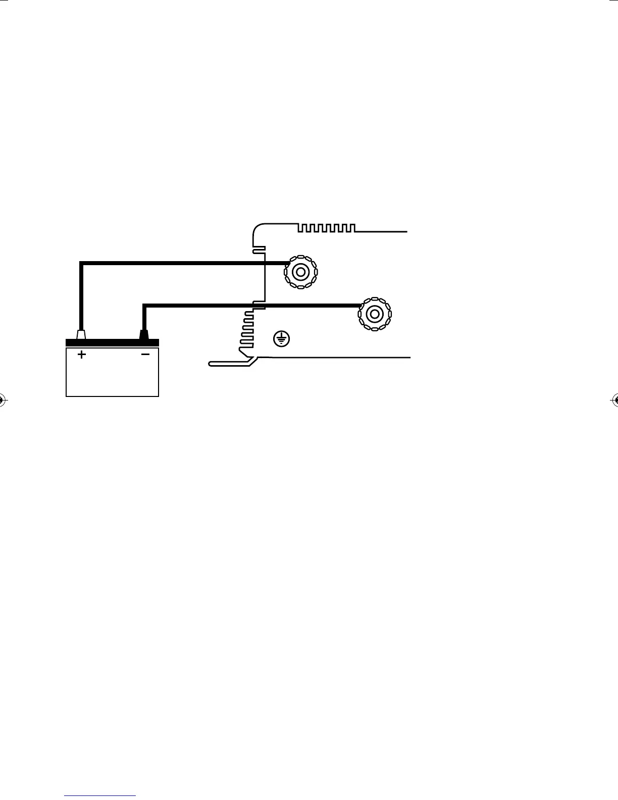
TEMPORARY CONNECTION:
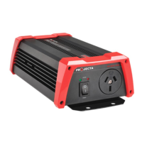
U Connect the ring terminal on the negative lead (Black) to the negative (Black) DC terminal on
the back of the inverter.
U Connect the battery clip (Black) or ring terminal (IM1000, IM2000) on the other end of the lead
to the negative DC supply or (-) battery terminal.
U Connect the ring terminal on the positive lead (Red) to the positive (Red) DC terminal on the
back of the inverter.
U Connect the battery clip (Red) or ring terminal (IM1000, IM2000) on the other end of the lead
to the positive DC supply or (+) battery terminal.
INPUT
POS.
CHASSIS
GND
INPUT
NEG.
+
–