93-509-09 - Issue 2 Rev 2 Page 14 of 20 Copyright Protec Fire Detection PLC
I
I
N
N
S
S
T
T
A
A
L
L
L
L
A
A
T
T
I
I
O
O
N
N
P
P
R
R
O
O
C
C
E
E
D
D
U
U
R
R
E
E
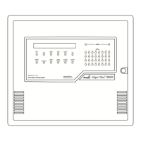
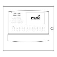
4.1 CONTROL PANEL
The 6300 is supplied complete and fully assembled in one box. The box also contains an installation template
showing mounting hole & cable entry positions with spirit level and plumb bob references.
1) Unpacking.
Remove the installation template from the packaging - leaving the 6300 unit in the box for protection.
2) Preparing the Mounting Position.
Use the installation template together with a spirit level etc. to mark, drill and plug the 3 mounting holes in the
desired position.
3) Removal of the Plastic Door.
Remove the 6300 unit from the packaging. Use the key supplied to unlock the outer plastic door, remove the
plastic door by extracting the hinge pins and place the door back in the box for protection.
4) Removal of the Inner Door.
Unscrew the 3 fixings on the metal inner door at the lock side of the door. Open the inner door and disconnect
the earthing point on the door and the wide ribbon cable that connects the main board on the door to the back of
the enclosure. Close the door and extract the 2 remaining hinge pins. Carefully remove the inner door from the
unit including all circuit boards fitted to it and place it back in the box for protection.
5) Removal of the battery clamp and gear-tray.
Remove the two screws holding the battery clamp (if supplied) and carefully withdraw the clamp ensuring that it
cannot short out the battery terminals. Remove the 2 screws from the bottom of the gear-tray (in the back of the
enclosure) and loosen the two at the top (key-hole fixings). Disconnect the earth connection from the gear-tray to
the enclosure. Remove the gear-tray from the enclosure including the attached circuit boards.
6) Preparing and Fixing The Unit.
Using the installation template, mark out suitable positions for cable entry on the back of the enclosure i.e. not
behind the gear-tray. Cut out the cable entry positions and mount the enclosure at the position prepared in (2)
feeding cables through into the box.
7) Re-fitting the gear-tray and battery clamp
Re-fit the gear tray (re-fit is reversal of 5). Ensure that the earth removed in (5) is re-connected DO NOT
CONNECT ANY NON-EARTH TERMINALS. Refit the battery clamp (refit is reversal of 5) ensuring that
the clamp cannot touch the battery terminals. DO NOT CONNECT THE BATTERIES
8) Re-fitting the Inner Door
Re-fit the inner door (re-fit is reversal of 4) ENSURE THAT ALL EARTHING POINTS ARE RE-
CONNECTED.
9) Re-fitting the Plastic Door
Re-fit the outer plastic door by offering the door up to the hinges and inserting the 2 hinge pins.