Do you have a question about the Protec Algo-Tec 6500 and is the answer not in the manual?
Outlines responsibilities for the named person overseeing the fire alarm system.
Daily checks required for the fire alarm system's operational status.
Procedures for performing weekly tests on the fire alarm system components.
Monthly testing procedures for the fire alarm system, including power checks.
Functions available to general users, including viewing system status.
Access for trained users to critical system functions and menu navigation.
Allows maintenance staff to exchange devices on the fire alarm loops.
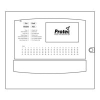
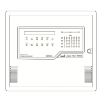
Explains the panel's LCD screen for displaying system status and information.
Describes the main indicators for Fire, Fault, Disable, and Test states.
Provides important fault and status information at a glance on the LCD.
Details how fire events are indicated by zone on the panel's indicators.
Indicates that a fire has been detected on one or more zones.
Shows a fire in a specific zone and is accompanied by panel buzzer.
Reports faults detected during the panel's internal software self-tests.
Indicates a fault on alarm devices connected to the loop or sounder circuits.
Signals a fault in the panel's power supply or internal batteries.
Reports a fault with the panel's auxiliary 24V supply output.
Prevents activation of alarm outputs like sounders in the event of a fire.
Inhibits activation and faults on the alarm routing output for fire events.
Prevents activation and faults on the fire protection equipment output for fires.
Indicates the panel is powered up from mains or batteries.
Shows when the panel is in test mode, either partially or fully.
Indicates the fire link path has been activated on the panel.
Shows the fire protection equipment path has been activated.
Indicates if alarm, fire link, or fire protection outputs are programmed with a delay.
Panel response when a detector activates, including indicators and output activation.
Panel response when a Manual Call Point is operated.
Refers to section 10.0 for details on coincidence/dependency modes.
How to silence alarm outputs by touching and holding the Silence button.
Procedure for resetting the panel after an alarm, including local reset of Call Points.
Describes the panel's display when no fires, faults, or tests are present.
Explains how to use the arrow buttons and Exit button to navigate menus.
How to use the keypad for entering numbers for zone lists or other data.
Option to print information if the panel is fitted with a printer.
How to select a specific panel in a multi-panel system.
How to select a loop card within a chosen panel.
How to select a specific loop associated with a loop card.
How to find and select a specific device on a selected loop.
Procedure for logging into the panel to access features and menus.
How the panel displays faults, disablements, or tests, and how to navigate them.
Describes the panel's display when a fire event is detected.
How to access the main user menu after logging in.
Displays options to show the system configuration, device details, and states.
Shows detailed information for individual devices, including sensitivity and state.
Displays algorithm data specifically for detector devices.
Provides a summary of device types across all loops for a selected panel.
Displays the current state (e.g., active, disabled) of devices on a loop.
Lists input groups and their current active or inactive states.
Lists output groups and their current active or inactive states.
Options to temporarily disable or enable input devices or outputs.
Displays a summary list of all current disablements on the system.
Allows disabling specific zones or types of devices within zones.
Options to disable individual devices on a loop.
Allows disabling specific output groups.
Options to disable various types of system outputs.
Disables the output used to signal a fire event to a remote monitoring centre.
Disables the output used to signal a fault event to a remote monitoring centre.
Disables outputs that trigger fire protection equipment.
Disables sounder devices that activate during a fire event.
Disables outputs controlling plant equipment shutdown on fire events.
Disables outputs not related to fire events.
Access to settings like time, date, configuration, and software versions.
Procedure for adjusting the panel's current time and date.
Displays the panel's site file configuration information.
Button to remove system faults; faults reappear if not fixed.
Displays panel cards and firmware versions for all panels.
Access to various testing options for the system.
Tests the panel's LCD, buzzer, and LED indicators.
Allows selecting specific zones for testing system response.
Configuration options for system tests, like alarm output behavior.
Puts the entire fire system into test mode for comprehensive checks.
Access to historical log options, including viewing fire and non-fire events.
Displays a list of all fire events recorded in the system log.
Displays all events from the log except fire events.
Allows filtering log events by type, such as fires or faults.
Shows the count of times the panel has entered the fire alarm state.
Access to options for printing system event logs and reports.
How to log in and access the Level 3a menu for device exchange.
Access to loop tools and printer menu options.
Provides access to options for exchanging loop devices.
Guides the user through the process of replacing loop devices.
| Brand | Protec |
|---|---|
| Model | Algo-Tec 6500 |
| Category | Control Systems |
| Language | English |