93-509-09 - Issue 2 Rev 2 Page 4 of 20 Copyright Protec Fire Detection PLC
I
I
N
N
T
T
R
R
O
O
D
D
U
U
C
C
T
T
I
I
O
O
N
N
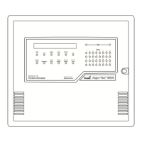
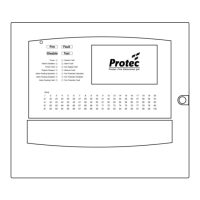
This document describes the methods to be employed when installing and connecting equipment associated with
the PROTEC 6300 FIRE ALARM CONTROL PANEL. The 6300 panel is produced with 1, 2 or 4 loops and this
manual is suitable for all versions.
1.1 THE 6300 SYSTEM
(REFER TO PID 203 – 6300 Example System Diagram)
Each addressable loop device has a unique Serial Number. The 6300 panel communicates with each device by
this Serial Number, and the device replies with an analogue value. This analogue value is interpreted by the
panel to determine the state of the device. The panel is therefore able to track accurately any changes in device
reply values and initiate any necessary actions.
The 6300 panel can drive up to 4 loops, each containing a maximum of 191 devices. No more than 512 detectors
and manual call points, spread across all four loops, may be fitted in order to comply with En54. Each device can
actuate an on-site-programmable set of outputs. 8 internal outputs are available (4 monitored, 2 non monitored
changeover contacts, a monitored 24V fire station output and a non-monitored fault changeover contact). It is
also possible to have an output on any address point using ZONE/ALARM interface units and 16 Way I/O
Boards.
It is possible to network up to 31 panels/repeaters. Networked panels/repeaters use a separate network card
mounted on top of the terminal board. They are connected together using an RS485 loop (refer to PID 194).
If networking is not used then a 4 core communication link (2 data + 2 power) can be used to provide an RS485
serial link to a maximum of 4 repeat panels.
1.2 ‘6000 SERIES’ LOOP
Each 6300 has the capability to communicate with Protec ‘6000 Series’ loops.
Each addressable loop device has a unique Serial Number. The 6300 panel communicates with each device by
this Serial Number and the device replies with an analogue value. This analogue value is interpreted by the panel
to determine the state of the device. The panel is therefore able to track accurately any changes in device reply
values and initiate any necessary actions.
The installer must mark up on the ‘as fit’ drawings the panel number (if more than one), loop number and
address of each device. This information will be required in section 6.2.