6.0 Installation
(cont’d)
6.5.1 Fully Ducted System (as illustrated in Section 5.1)
Stale air exhaust ductwork:
• Install registers in areas where contaminants are produced: kitchen, bathrooms, laundry
room, etc.
• Install registers 6 to 12 inches (152 to 305 mm) from the ceiling on an interior wall OR install
them in the ceiling.
• Install the kitchen register at least 4 feet (1.2 m) from the range top.
• If possible, measure the velocity of the air flowing through the registers. If the velocity is higher
than 400 ft/min. (122 m/min), then the register type is too small. Replace with a larger one.
Fresh air distribution ductwork:
• Install registers in bedrooms, dining room, living room and basement.
• Install registers either in the ceiling or high on the walls with air flow directed towards the ceiling.
(The cooler air will then cross the upper part of the room, and mix with room air before descending
to occupant level.)
• If a register must be floor installed, direct the air flow up the wall.
6.5.2 Exhaust Ducted System (Source Point Ventilation) (as illustrated in Section 5.2)
Stale air exhaust ductwork: (same as for Fully Ducted System, described in point 6.5.1)
Fresh air distribution:
There are two methods for connecting the unit to the furnace:
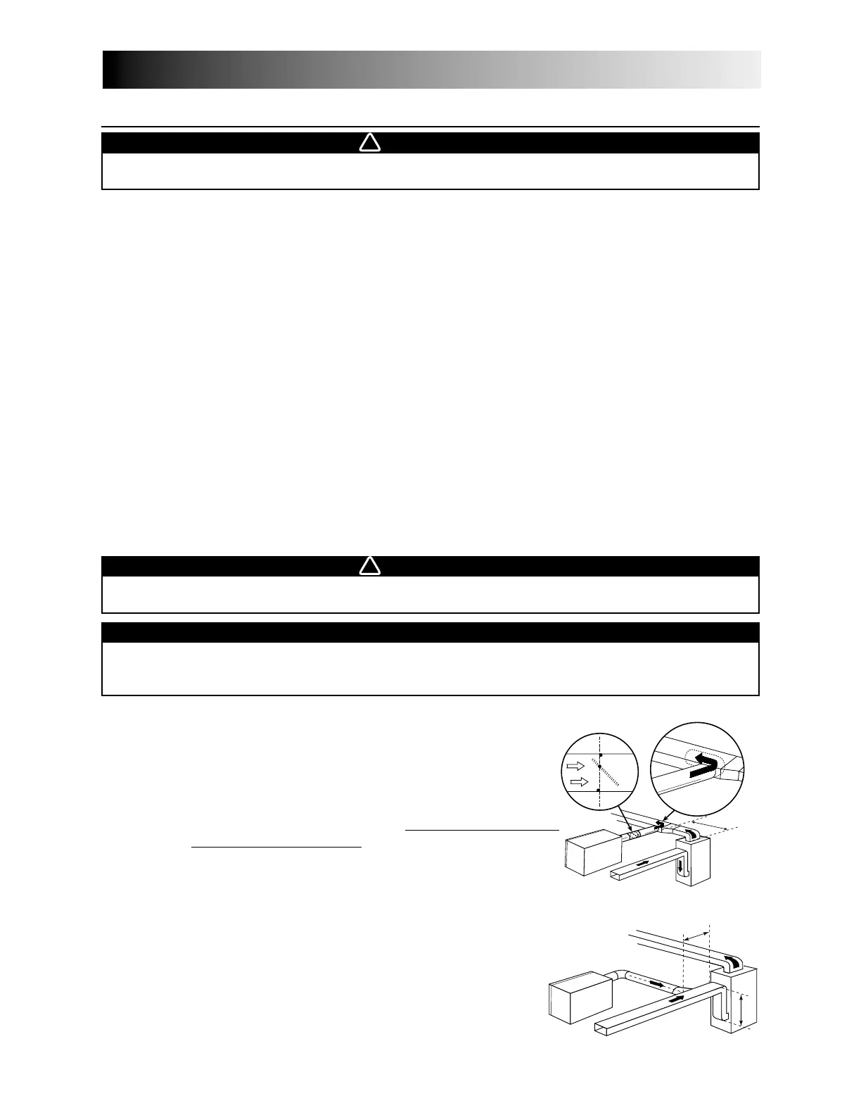
Method 1: supply side connection
• Cut an opening into the furnace supply duct at least
18 inches (0.5 m) from the furnace.
• Connect this opening to the fresh air distribution port
of the HRV/ERV (use steel duct, see figure 10).
• Make sure that the HRV/ERV duct for
ms an elbow
inside the furnace ductwork.
• If desired, interlock (synchronize) the furnace blower
operation with the HRV/ERV operation.
(See Section 8.4).
Method 2: return side connection
• Cut an opening into the furnace return duct not less than
10 feet (3.1 m) from the furnace (A+B).
• Connect this opening to the fresh air distribution port of
the HRV/ERV (see figure 11).
NOTE: For Method 2, it is not essential that the furnace
blower runs when the HRV/ERV is in operation, but
we recommend it. If desired, synchronize the furnace
blower operation (see Section 8.4).
6.5 I
NSTALLING THE
D
UCTWORK AND
R
EGISTERS
WARNING
Never install a stale air exhaust register in a room where a combustion device is, such as a gas
furnace, a gas water heater or a fireplace.
WARNING
When performing duct connection to the furnace, installation must be done in accordance with all
applicable code sand standards. Please refer to your local building code.
CAUTION
When performing connection to the furnace supply duct, this duct must be sized to support the
additional airflow produced by the HRV/ERV. Also, use a steel duct with a backdraft damper to
prevent the risk of overheating the HRV/ERV.
VD0040
B
A
VD0041
minimum
18” (0.5 m)
Steel duct with
backdraft damper
A+B= not less
than 10’ (3.1 m)
figure 10
figure 11
16