24
W R G
Y
W
R
G
C
Y
9
8
7
6
5
4
3
2
1
HRV CONTROL CONNECTOR
THERMOSTAT
TERMINALS
FOUR
WIRES
I OC OL Y R G BF F
J3
TWO WIRES
heating only
FURNACE
24-VOLT
TERMINAL BLOCK
TWO WIRES
COOLING SYSTEM
VE0010A
Standard furnace interlock wiring
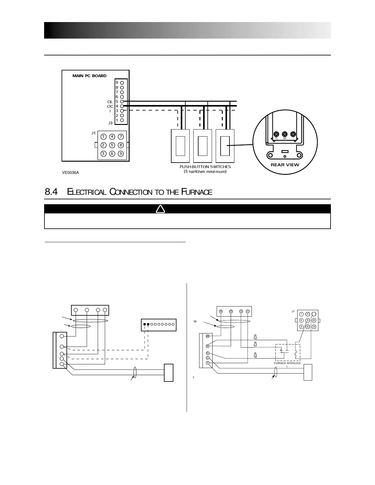
8.3 E
LECTRICAL
C
ONNECTION TO
O
PTIONAL
C
ONTROLS
8.0
Installation of the Controls (con’d)
9
8
7
6
5
4
3
2
1
OL
O
C
I
1
4
7
2
5
8
3
6
9
J
3
MAIN
PC
BO
A
RD
PUSH-BUTT
O
N SW
I
T
C
HES
(
5
switches maximum)
J
1
VE0036A
REAR VIEW
8.4 E
LECTRICAL
C
ONNECTION TO THE
F
URNACE
WRGY
W
R
Y
R
G
Y
C
J1
1
2
4
5
6
8
93
*FURNACE INTERLOCK
RELAY
NC NO
7
COM
7
THERMOSTAT
TERMINAL
Unit Control Module
4 WIRES
2 WIRES
heating only
wiring
nuts
FURNACE
24-VOLT
TERMINAL BLOCK
2 WIRES
COOLING SYSTEM
GRAY BROWN
RED
GREEN
BLUE
9-PIN AMP PLUG
*FURNACE INTERLOCK RELAY, PART # 12658
VE0009A
Alternate furnace interlock wiring
For a furnace connected to cooling system:
On some older thermostats, energizing the “R” and “G” terminals at the furnace has the effect of energizing
“Y” at the thermostat and thereby turning on the cooling system. If you identify this type of thermostat, you
must use the “alternate furnace interlock wiring”. An additional control relay will then have to be installed.
WARNING
Never connect a 120-volt AC circuit to the terminals of the furnace interlock (standard
wiring). Only use the low voltage class 2 circuit of the furnace blower control.