7
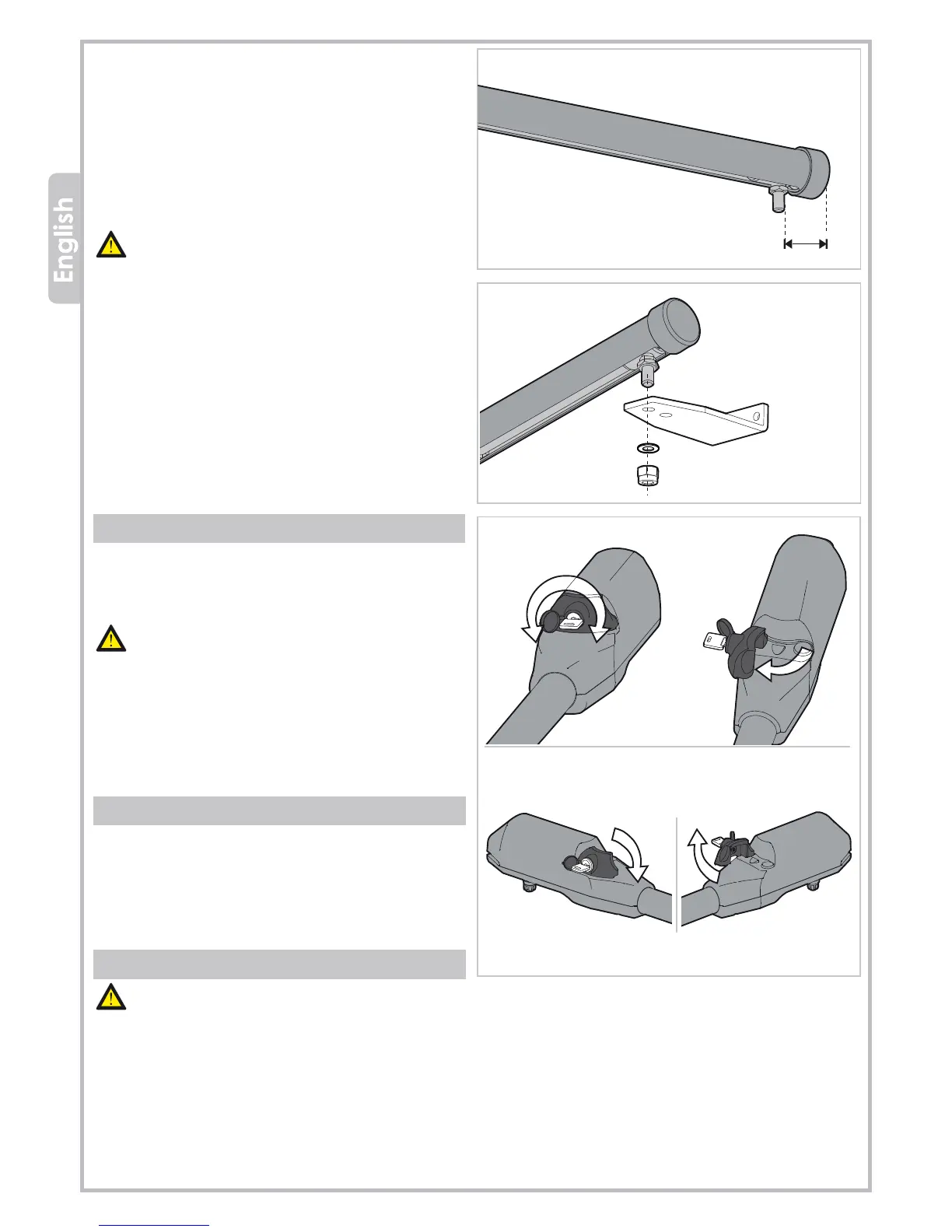
Fig. 15
Fig. 17
45 mm
Fig. 16
S4
M12
3.6.2 ACE TA
To determine the position of bracket S4:
- Put the gate in closing position
- Release the gearmotor
- Slide the front drive pin to the closing limit-switch point
(keep a distance of 45 mm between the pin and the
pipe end terminal (see picture 15).
- Fix the bracket S4 to the drive pin (see picture 16).
- Fit the bracket S4 onto the gate and keep the motor
horizontal. Fix or weld.
Check the manual opening of the leaf before defini-
tively fixing the bracket to make sure the gate can
open fully to your required anglee.
4. RELEASING THE GEARMOTOR
- Insert the key and turn it 90° clockwise (see picture 17).
- Pull the release handle inwards to unlock the LH motor
and outwards to unlock the RH motor.
The gate can be locked in any position after the first
start command the system will return to its default
settings.
5. MAINTENANCE
Functional checks must be performed once every 6
months, including: checking the state of lubrication and
tightness of the anchoring screws on the operator as well
as the good operation of all safety devices.
6. DISMANTLING AND DISPOSAL
DO NOT DISPOSE OF IN NATURE!
Some components may contain hazardous waste.
They must, thus, be removed and turned into licensed firms
for their disposal.
Before acting always check the local laws on the matter.
INNER VIEW
OUTER VIEW
LH RH