4
BB
B
B
50 mm
345 mm ACE 3 TI
445 mm ACE 4 TI
Fig. 3
Fig. 4
Fig. 5
Fig. 6 Fig. 7
Fig. 2
50 mm
445 mm
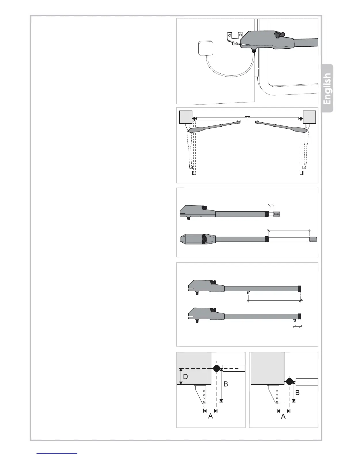
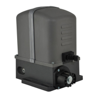
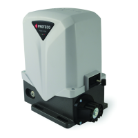
3.3 ESTABLISHING RH AND LH OPERATOR
The ram operators are supplied handless version, it means
they can be installed either on the right or left side of the
gate (see picture 3).
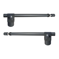
ACE TI
Gate in closing position - inox pipe maximum extension:
Ace 3 = 345 mm
Ace 4 = 445 mm
Gate in opening position - inox pipe minimum extension 50 mm
(see picture 4).
ACE TA
Gate in closing position: minimum distance 50 mm.
Gate in opening position: maximum distance 450 mm.
(see picture 5)
3.4
FASTENING THE GEARMOTOR
3.4.1 Vertical positioning quota
a)
If the gate is sturdy you can fit the gearmotor wherever
it goes, at any height from ground.
b) If the gate is particularly light fit the gearmotor as close
as possible to gate centerline.
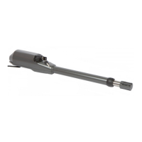
3.4.2 Horizontal positioning quota
Gate leaf hinged in the center of the pillar (see picture 6).
Gate leaf hinged on the corner of the pillar(see picture 7).
Best of performance is obtained respecting A and B
dimensions, see picture 8 (opening angle 90°).
LEFT HAND
operator
RIGHT HAND
operator
B = Mechanical ground stops
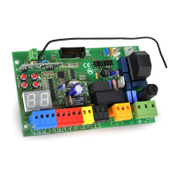
• Cut off the power before starting wiring.
• Make sure you have set up a suitable dual-pole cut off
device ( 3 mm wires) along the power supply.
• Make sure you have suitable tubing and conduits for the
electrical cables: connect the motors, control panel and
accessories using separated currugated tubes, in order to
prevent interferences that may result in bad operation.
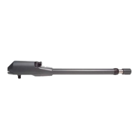
• Fit the power cable keeping a curve as shown in picture 2,
in order to avoid water blackflow inside the operator.
• All opening commands and safety devices must be free of
tension (dry contact).
opening position
closing position