+
-
Q26 _03_17 2
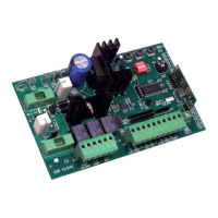
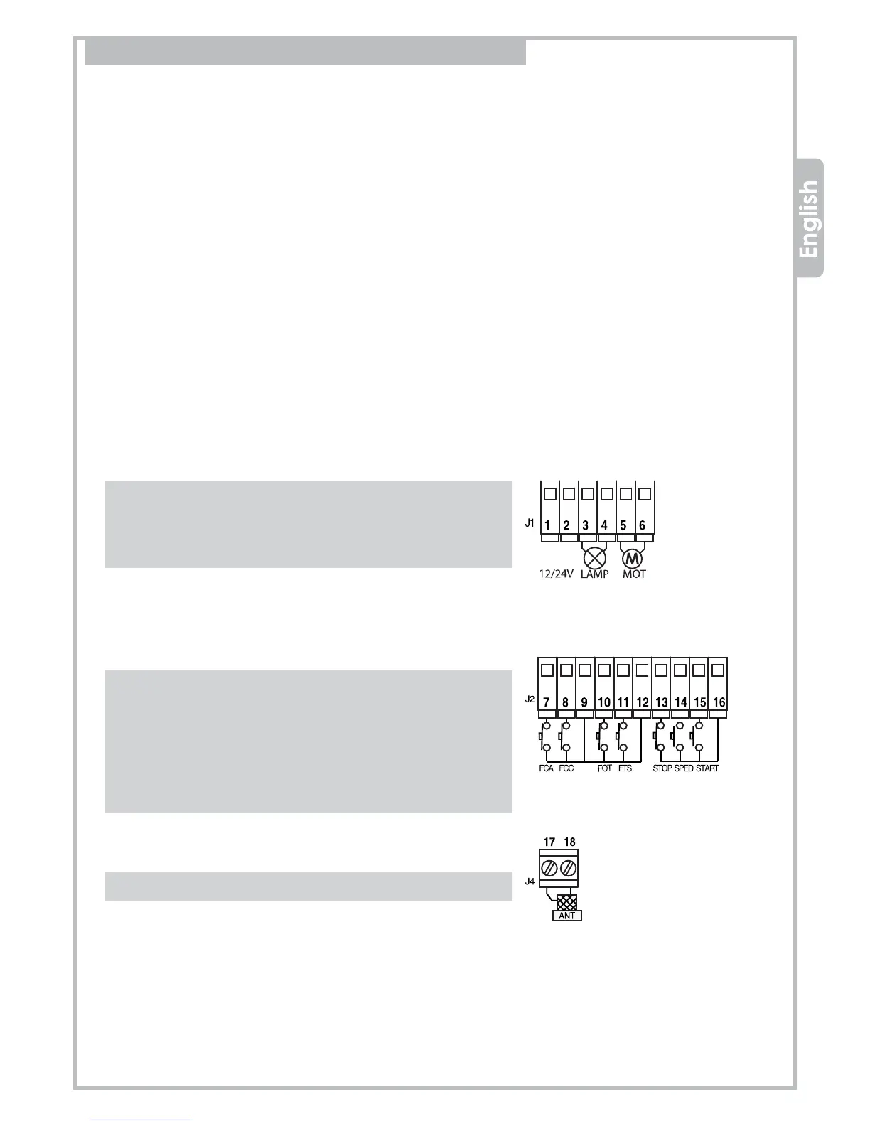
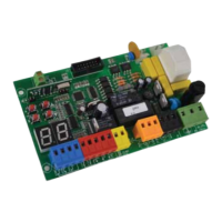
2. WIRING DIAGRAM and COMPONENTS
DL1 = Programming LED
DL2 = OPENING LIMIT SWITCH signalling LED
DL3 = CLOSING LIMIT SWITCH signalling LED
DL4 = CLOSING PHOTOCELLS status. LED lit up once the photocells have been correctly wired.
DL5 = OPENING PHOTOCELLS or other SAFETY DEVICES status.
LED lit up when additional set of photocells or other safety device is correctly wired.
DL6 = Emergency STOP button status. LED lit up once the emergency stop push button has been correctly wired.
DL7 = PEDESTRIAN START command. The LED lit up when a pedestrain start command is given
DL8 = START command signalling light. LED lit up when a start command is given
DL9 = 230V mains light. Led lit up when the control panel is powered.
P1 = Radio transmitter MEMORY button
P2 = WORKING TIME setting button
P3 = PAUSE-TIME setting button
RV1 = DECELERATION SPEED adjuster
FS1-FS2 = Input for back-up BATTERY
FS3-FS4 = Secondary input for TRANSFORMER
F1 = Fuse for battery 10A
F2 = Fuse for service devices 0.8A
JP1 = Battery-charger jumper 12/24V
JP2 = Jumper for accessories output 12/24V
DS1 = Switches for the operating mode selection
IC7 = Radio-receiver module
J1 = plugs for POWER devices
1 POSITIVE (+) 12/24Vdc for accessories power supply
2 NEGATIVE (-) 12/24Vdc for accessories power supply
3 output for flashing light (Blinker) power supply
4 output for flashing light (Blinker) power supply
5 output for 12Vdc or 24Vdc motor
6 output for 12Vdc or 24Vdc motor
J2 = plugs for CONTROLS and SAFETY DEVICES
7 input for OPENING LIMIT-SWITCH (N.C. contact)
8 input for OPENING LIMIT-SWITCH (N.C. contact)
9 COMMON inputs
10 CLOSING PHOTOCELLS input (N.C. contact)
11 OPENING PHOTOCELLS input (N.C. contact)
12 COMMON inputs
13 STOP push-button input (N.C. contact)
14 PARTIAL OPENING push-button (N.O. contact)
15 START push-button (N.O. contact)
16 COMMON inputs
J4 = plugs for external AERIAL
17 aerial cable (EARTH)
18 aerial cable (SIGNAL)