- 22 -
Note:
The number of teeth is imprinted on all change gears.
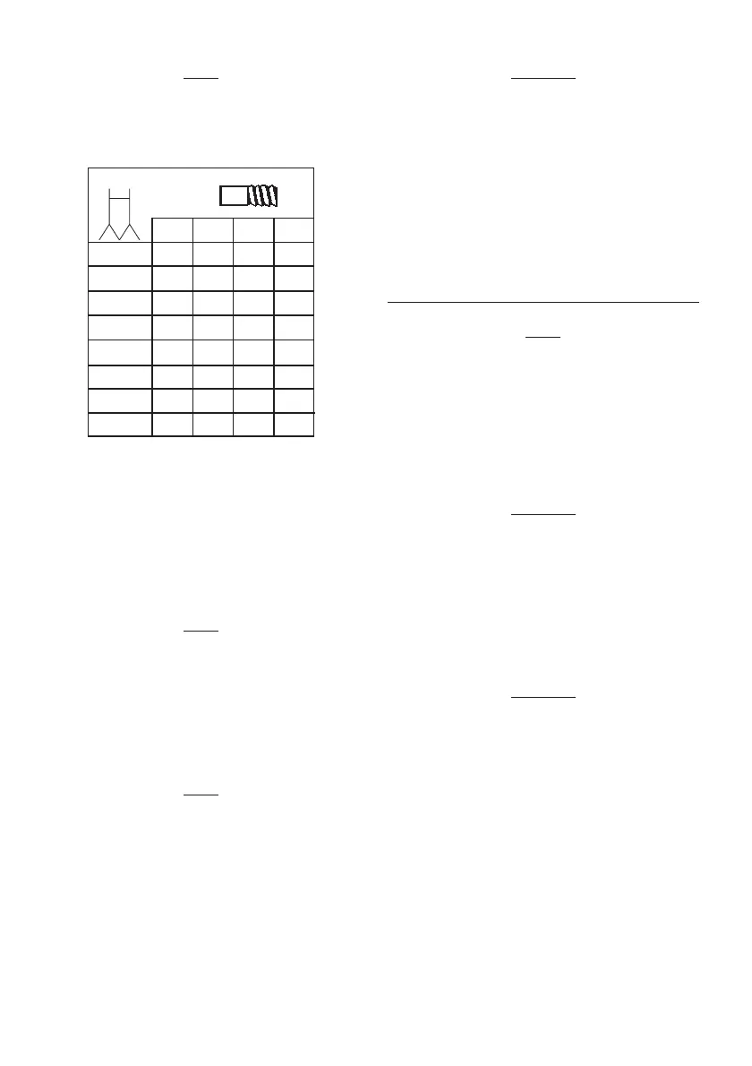
For example, if cutting a thread with a pitch of 1.0 mm, the
table on the drive gearbox will show the following data:
W 15 - gear on the main spindle with 15 teeth. This gear is
already installed on the shaft and must not be replaced.
Z
1
15 - Z
2
20 - Intermediate gear for the toothed belt of the
main spindle with 15 teeth and permanently linked gear for
the leadscrew with 20 teeth.
L20 - leadscrew gear with 20 teeth.
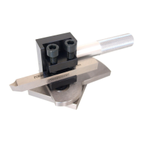
3. Fasten the change gear "Z
1
-Z
2
" with 15/20 teeth (Fig. 19)
to the gear arm 3 using the screw 2, pulley, reduction
sleeve and nut.
Note:
Do not yet tighten the fastening screw nut 2 (off-centre adjust-
ment must still be possible).
The change gear "Z
1
-Z
2
" runs freely between pulley and slee-
ve.
The washer prevents the toothed belt from becoming deta-
ched from the gear "Z
1
".
4. Release the set screw 1, remove the change gear "L40"
and replace with the change gear "L20".
Note:
The grain of the leadscrew change "L" must always point to
the lathe chuck.
The set screw 1 must be clamped onto the flattened part of
the shaft.
Important
To ensure that there is sufficient play between the change
gears, always insert a strip of newspaper between the teeth
when pushing the change gears together. The thickness of
the newspaper should correspond to the required tooth play.
5. Push the axle of the change gear "Z
1
-Z
2
" onto the arm so
that it contacts the leadscrew gear "L" and then tighten
the fastening screw nut 2.
6. Position the short toothed belt for the connection between
the gears "W" and "Z
1
" on the main spindles.
7. Push the gear arm 3 downwards and tighten the clamp
screw 4.
Thread cutting with the turning tool
Note:
For the following operations, the work piece must be machi-
ned completely and have the correct thread outer diameter.
It is advisable to work out a chamfer at the beginning of the
thread. The thread turning tool must be clamped at an angle
of 90° exactly.
1. Clamp the work piece.
2. Switch off the automatic feed and set the turning tool to
the starting position.
Important
Use the lowest speed when cutting threads and proceed with
utmost caution.
3. Press button 2 (Fig. 20) to switch on the machine (clock-
wise rotation).
4. Advance the turning tool on the cross-slide 1 and engage
feed 3.
5. Switch off the machine when the required thread length
has been reached 2.
Important
The automatic feed must remain switched on until completi-
on of the thread. Disengaging between individual steps
renders further work impossible.
Only switch over the motor switch once the lathe chuck has
come to a complete standstill. Switching over immediately
increases wear and reduces the service life of the motor.
mm
W Z
1
Z
2
L
0.5 15 15 20 40
0.625 15 15 25 40
0.7 15 15 28 40
0.75 15 15 30 40
0.8 15 15 32 40
1.0 15 15 20 20
1.25 15 15 25 20
1.5 15 15 30 20
n v
 Loading...