- 24 -
Collet chuck attachment and collet
chucks
Note:
T
he collet chuck unit is especially suitable for processing round
p
arts with great precision. The concentricity is considerably
greater than when working with a jaw chuck.
1. Remove three fastening screws from the three-jaw chuck and
remove chuck.
2
. Thoroughly clean the fit for the collet chuck mount 2
(Fig. 22) and the fit in the main spindle 1.
3. Attach the collet chuck mount 2 using four fastening
screws 3.
Important
Always use the correct collet chuck to suit the work piece.
Chucks with an oversized diameter are destroyed.
4. Insert the collet chuck 6 and loosely attach the union nut 5.
Important
Never tighten the union nut when there is no work piece
inserted. Remove the pins 4 for tightening the union nut 5
immediately after tightening.
5. Insert the appropriate work piece in the collet chuck and tight-
en the union nut 5 using the tool pins 4.
Fixed steady rest
The steady rest is particularly suitable for hollowing out long work
pieces with diameters up to 50 mm.
1. Release the fastening screw 4 (Fig. 23) and position retaining
plate 3 laterally.
2. Place the steady rest on the bed guide and set to the desired
position.
3. Swivel the retaining plate 3 parallel to the steady rest base and
tighten fastening screw 4.
4. Release all clamp screws 1 and drive the individual retaining
jaws 2 onto the workpiece.
Important
The jaws 2 must only touch the work piece and must not
clamp it. Otherwise there is a risk of the work piece
surface becoming scratched and the motor becoming over-
loaded.
If the work piece is not round and smooth at the support point, it
must first be turned round. Lubricate the jaws and work piece
regularly when turning.
5. Check that the work piece is positioned in the steady rest free
of play and re-tighten clamp screws 1.
Travelling steady rest
Installation identical to the fixed steady rest, but this steady rest is
attached to the support (Fig. 24).
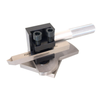
Faceplate with clamps
This is installed in place of the lathe chuck. Ideal for clamping
larger and asymmetrical workpieces. Ø 150 mm. 2 continuous T-
grooves. incl. clamps.
EC Declaration of Conformity
Name and address:
PROXXON S.A.
6-10, Härebierg
L
-6868 Wecker
Product designation: PD 400
Article No.: 24400
I
n sole responsibility, we declare that this product conforms to the
following directives and normative documents:
EU EMC Directive 2004/108/EC
DIN EN 55014-1 / 05.2012
D
IN EN 55014-2 / 11.2014
DIN EN 61000-3-2 / 03.2015
DIN EN 61000-3-3 / 03.2014
EU Machinery Directive 2006/42/EC
DIN EN 62841-1 / 07.2016
D
ate: 30.09.2021
Dipl.-Ing. Jörg Wagner
PROXXON S.A.
Machine Safety Department
The CE document authorized agent is identical with the signatory.
 Loading...