- 23 -
Setting the guide play
Regular lubrication of the guides does not prevent evidence of
p
lay in the guides after a certain amount of time.
1. Release adjustment screw lock nuts 1 (Fig. 18) for the top slide
2, screw in all adjustment screws 3 evenly until play is eliminat-
ed and re-tighten the lock nuts.
2
. Repeat this procedure for cross-slide 4.
Note:
The guide can be clamped using screw 5.
3
. Turn the machine upside down and unscrew stud 1
(Fig. 19) slightly.
4. Tighten clamping screws 2 slightly to reduce the play.
5
. Check whether the support can still be pushed easily. If the
support is difficult to move, increase the play a little.
Main spindle
The 2 taper roller bearings of the spindle are maintenance-free
for at least 6000 hours at minimum speed and 1800 hours at
maximum speed. If slight play is evident after this period, the
bearings can be adjusted by a specialist.
Overload protection of lead spindle
In the event of jamming or other overload during operation of the
machine with automatic feed, the shear pin (see exploded view of
assembly group 02 “Bed with lead spindle”, Pos. 23) in the lead
spindle could break.
This is designed as a predetermined break point and must then
be replaced (shear pin can be obtained from us as a spare part).
he wheel arm with the change gears must be removed. To do so,
loosen screw 1 (Fig. 13) and pull off arm 2 together with the
change gears.
Now the screws Pos. 29 (exploded view) can be unscrewed and
the unit Pos. 26 can be removed together with the add-on com-
ponents.
The remains of the destroyed shear pin are expelled from the
lead spindle components with a suitable tool (drift punch, mandrel
or similar).
The components are then reassembled. Please note: The holes
must be aligned so that the new shear pin can be driven into the
intended opening.
Make sure that the pin is seated only on one side so that it is only
subjected to shear stress on one side.
Now the whole unit can be reinstated. If it turns out that the shear
pin protrude too far from its opening, the protruding end can be
cut off or ground off.
Disposal:
Please do not dispose of the device in domestic waste! The
device contains valuable substances that can be recycled. If you
have any questions about this, please contact your local waste
m
anagement enterprise or other corresponding municipal facili-
ties.
Accessories for Lathe PD 400
Note:
T
he following accessories are not included in the standard equip-
m
ent.
Important
Before installing accessories, switch off the machine at the main
s
witch.
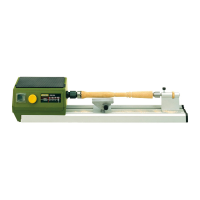
Centre turning attachment
Installing the centre turning attachment:
Note:
L
onger work pieces are clamped between the brad points of the
main spindle and tailstock. The work piece must be
provided with a centre bore on both faces.
An exactly cylindrical work piece is only achieved if the points
align in the horizontal position.
1. Remove three fastening screws from the three-jaw chuck and
remove chuck.
2. Thoroughly clean the fit for the drive plate 3 (Fig. 20), the cen-
trepoint 1 and its fit in the main spindle.
3. Insert the centrepoint 1 in the fit of the main spindle. Insert the
second centrepoint in the tailstock.
4. Insert adapter 4 in the drive plate 3 and tighten the stud lightly.
Push both over the workpiece 5. Screw driver 2 into the spin-
dle flange.
5. Clamp the workpiece between the centrepoints. Push drive
plate 2 (Fig. 21) over the driver and fasten to the workpiece
using Allen key 1.
Important
When using a centre fixed to the tailstock, regular lubrication of
the centre and centre bore is necessary to prevent overheating
due to friction.
Removing the centrepoint:
6. Guide a suitable aluminium or brass rod through the main spin-
dle from left to right.
7. Hold the centre and release by lightly tapping the rod.
4-jaw chuck with individually adjustable
jaws
Attention!
Follow the instructions in the enclosed operator's manual
provided by the manufacturer of the chuck.
4-jaw chuck (concentrically clamping)
Attention!
Follow the instructions in the enclosed operator's manual
provided by the manufacturer of the chuck.
 Loading...