9. Status Display / Operating Element / Communication
9.1 Status LEDs
9.2 Commissioning button
9.3 Communication Port
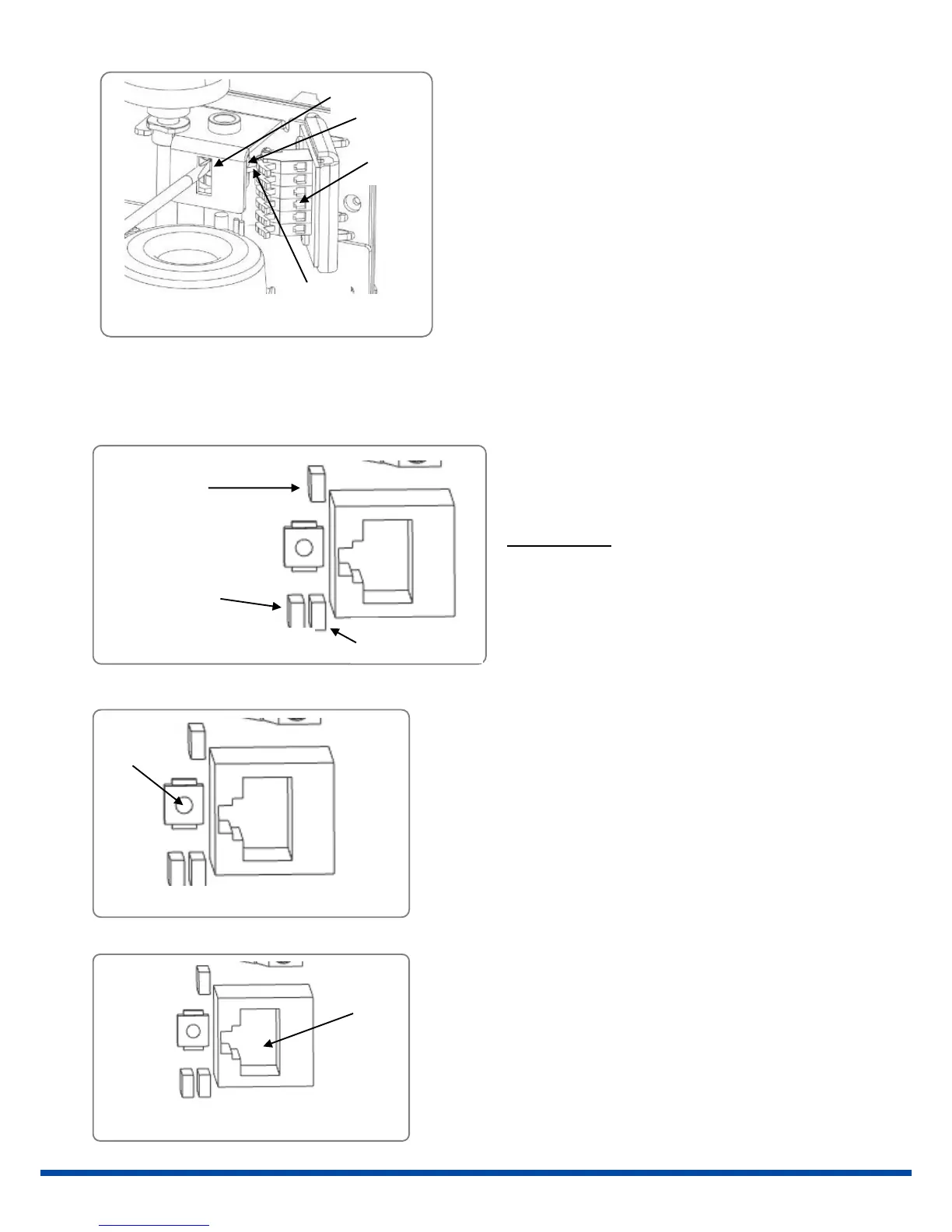
Red LED for
status indication
Figure 18: Adjusting the cams
The cams for activating the switches are mounted
on a shaft by means of a friction coupling. They are
adjustable by a screwdriver with a small end, using
the bride (3) as support. At actuators closing
clockwise, the lower cam (1) activates the switch for
closing direction, the upper cam (2) for opening
direction.
Figure 20: Commissioning button
The commissioning button for starting the
automatic commissioning run (to adjust the
actuator to the valve) is located beside the LEDs.
-> See chapter 10.1 “Cut-off in end positions” and
11.1.2. “Commissioning Procedure”
Figure 21: Communication port
Unscrewing the cap reveals a red and a green LED to
indicate the status of the actuator.
Option Feldbus:
Another single red LED (optional) signals the status
of the optional fieldbus interface. -> See special
operating manual for AMS-Fieldbus
Communication and parameterising via computer is
done using a special communication cable to a RJ45
socket. All actuator parameters are adjustable using
the communication software PSCS.
-> See operating instruction PSCS.
Red LED for
fieldbus display
Green LED for
status indication
 Loading...