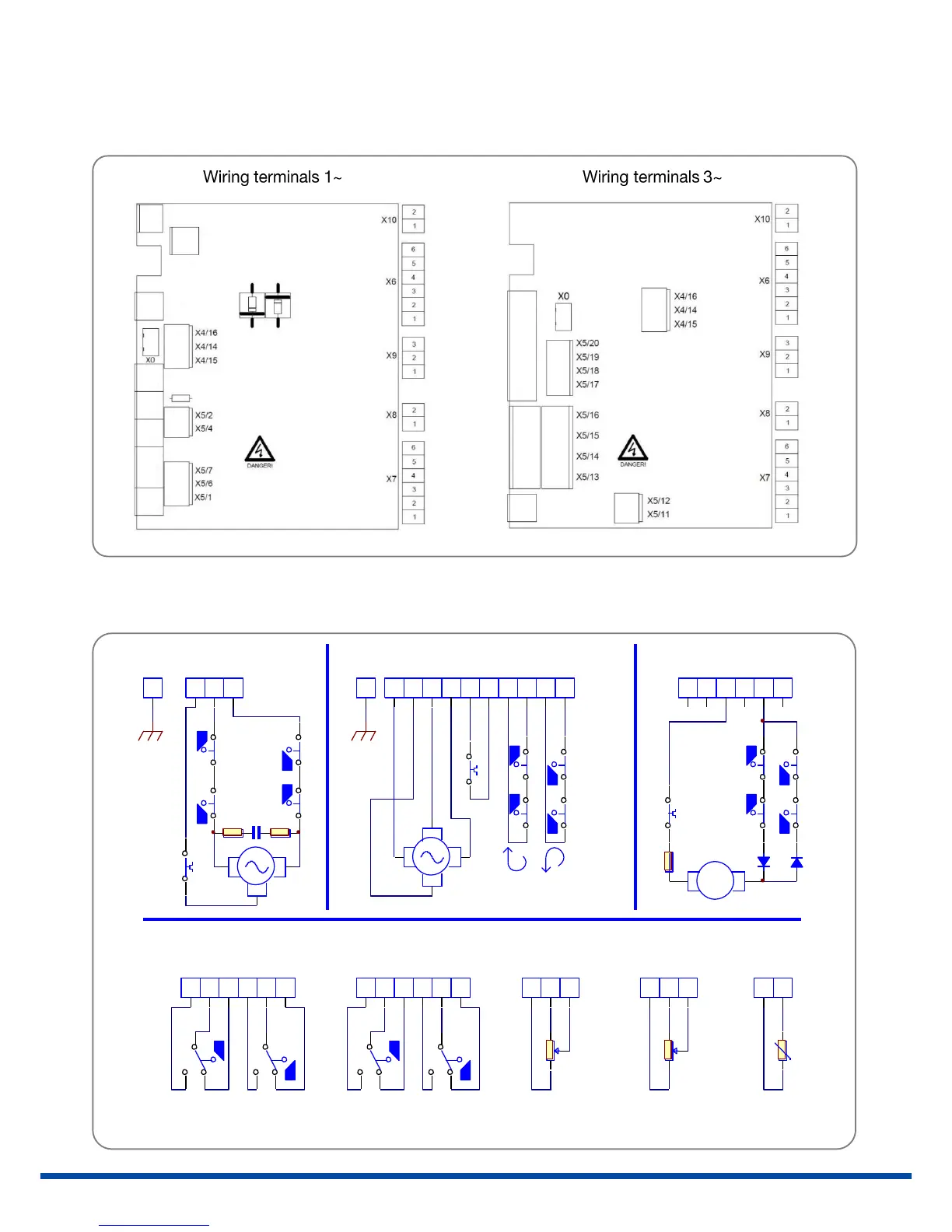
11.1 Wiring diagram
Figure 12 indicates the wiring diagrams for standard actuators. However, the wiring diagram inside the actuator
cover is relevant for the specific actuator. See the separate wiring diagram in the corresponding service instructions
for any set of accessories.
Figure 11: Wiring terminals
X0 = Potentiometer, internal wiring
X10 = Normally OPEN contact option
Figure 12: Wiring diagram
1 2 3 4
A
B
C
D
4321
D
C
B
A
Error : Log oPS .b mp file no t foun d.
PSQ Übersicht
5-Jan-2011
1
1
PSQ_Übersicht_Anschlussplan_C.Sch
Alle Rechte vorbehalten All rights reserved
P roje kt
S cha ltplan Nr.
B earbe itet
Geprüft
Freige geb en
Index Änderu ng Name Datum
Blatt
von
Name Datum
Gedruckt am
PS Automation GmbH
P hill ipp-K rä m er-R ing 13
67 090 B ad Dürkhe im
Vervielfältigung, Weitergabe an Dritte nur mit
schriftlicher Genehmigung
Filena m e
15:54:43
P .B ernh art
02 .04.04
3
1
2
4
6
5
X6
L
R
S
Potentiometer 1
Potentiometer 1
Additional
Zusatzwegs chalter
Additional
12V/24V DC
Zu / Close Auf / Open
Position Sw itch
14
15
16
X4
13
14
15
16
11
12
17
18
19
20
X5
L
R
S
Potentiometer 2
Potentiometer 2
Additional
1
2
3
X9
t
PE
L3
L1
L2
N
1
2
4
X5
PE
N
L2
L1
t
3-Phasen Drehstrom1-Phasen Wechselstrom
1
2
X8
Heizung
Heating
t
3-Phase a.c.1-Phase a.c.
Index C
3
1
2
4
6
5
X7
Zusatz Drehmo. Schalter
Additional
Zu / Close Auf / Open
Torque Switch

 Loading...