Do you have a question about the PS Engineering PAR200A and is the answer not in the manual?
Overview of the PAR200A system, its features, and manual scope.
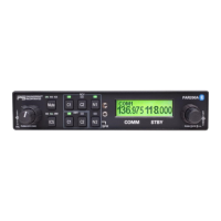
Details on the PAR200A audio selector panel, intercom, and VHF control capabilities.
FAA and EASA certifications for the audio selector and VHF transceiver.
Technical specifications for the audio selector and intercom functions.
Technical specifications for the VHF communications transceiver.
Operating temperature, altitude, weight, and physical dimensions.
Details on the electrical power needs and maximum current for the audio panel.
Impedance, isolation, and output characteristics for the audio selector.
Details on intercom positions, inputs, muting, distortion, and frequency response.
Technical details for the TY91L VHF Transceiver.
Radio type, channels, frequency range, and power output details.
Dimensions, weight, FCC ID, and electrical specifications.
List of supplied PAR200A units and associated Trig VHF transceivers.
Details of the components included in the standard installation kit.
Circuit breakers and power connections required for installation.
Headphone/microphone jacks, headphones, and VHF antenna requirements.
Mounting hardware and interconnect wiring specifications.
Guidance on aircraft radio station licensing for domestic and international operations.
Scope of installation procedures and certification requirements.
Steps for handling, inspecting the unit for damage, and reporting issues.
General procedures and considerations for installing aircraft equipment.
Specific instructions for mounting the remote TY91/TY92 VHF transceiver.
Steps for installing the audio panel into its mounting rack.
General instructions for assembling and installing cable harnesses.
Discussion of electrical noise sources and mitigation techniques.
Specifics on connecting music inputs and minimizing noise interference.
Details on assembling the audio panel tray and its connectors.
How the audio panel interfaces with standard aircraft avionics.
Details of the 25-pin connector for the TY91/TY92 VHF transceiver.
Configuration options for using the transceiver as COM 1 or COM 2.
Recommendations for routing antenna cables to minimize interference and VSWR.
Procedure for attaching the antenna cable to the TNC connector.
Considerations for optimal placement of the VHF communications antenna.
Explanation of the importance of a ground plane for monopole antennas.
Overview of using cellular phones with Bluetooth via the PAR200A.
Steps for pairing separate Bluetooth music and telephone devices.
Note regarding FCC regulations on cellular phone usage in aircraft.
How to adjust or disable telephone sidetone using switch settings.
Description of swap mode and automatic backlighting control.
Details on the available unswitched inputs and their presentation.
Table detailing unswitched inputs, fail-safe, crew headset, and gain.
General guidelines for intercom wiring connections using specific cable types.
Interconnection details for the 8-station IntelliPAX expansion unit.
How to connect music inputs and minimize noise interference.
Enabling Music 1 for all passenger headsets via a switch.
Explanation of the SoftMute™ system for music muting during communications.
Control for Music 2 mute and safety precautions for entertainment devices.
Diagram illustrating the locations of various adjustment controls on the unit.
Procedure for reducing intercom microphone input gain in noisy environments.
Table showing DIP switch configurations for microphone gain settings.
Guidance on optimal placement of the VHF antenna for best results.
How to adjust the radio sidetone level and squelch threshold.
Procedure for switching between 25 kHz and 8.33 kHz channel spacing.
Table providing example channel assignments when using 8.33 kHz spacing.
Detailed pin assignments for the J1 connector on the PAR200A.
Detailed pin assignments for the J2 connector on the PAR200A.
Steps for securely installing the unit into its mounting rack.
General operational checks for the PAR200A system after installation.
Ground verification procedures for the TY91/92 transceiver.
Flight testing procedures and checkout for the telephone function.
Final review of the installation for safety, interference, and mechanical compliance.
Introduction to operating instructions and explanation of the control layout.
How to power the unit on/off and its fail-safe operation.
Managing the TY91/92 radio power when integrated as COM 1 or COM 2.
How to adjust the intercom (ICS) and COM radio volumes.
How to select which COM radio to transmit on using C1 and C2 buttons.
Activating and using Split Mode and Swap Mode for transmissions.
How to select COM and Navaid receiver audio sources.
How to activate and use the cockpit speaker for audio output.
Introduction to the controls for the VHF transceiver on the right side.
How to select frequencies and store them in memory.
Steps for storing and recalling frequencies from memory.
How to enable or disable the automatic radio squelch function.
How to activate the monitor mode to listen to the standby frequency.
How monitor mode indicates activity and its operational behavior.
Procedure for switching to and tuning using 8.33 kHz channel spacing.
Example table of channel assignments for 8.33 kHz frequency spacing.
Explanation of the IntelliVox® system's automatic VOX-squelch operation.
Tips for optimal microphone placement and performance with IntelliVox®.
Considerations for using mono headsets in a stereo intercom installation.
How to select and understand the ISO, ALL, and CREW intercom modes.
Steps required to pair a Bluetooth-enabled phone with the PAR200A.
How the telephone function operates, including call handling and audio routing.
Important notes and warnings regarding cellular phone use in aircraft.
Details on music input sources and how they are distributed to headsets.
FAA regulations regarding the use of portable electronic devices during flight.
Explanations of MUTE ON, RADIO MUTE, INTERCOM MUTE, and MUTE OFF modes.
How to control Music 2 mute and activate Karaoke Mode for passengers.
Procedure for adjusting the contrast of the LCD display.
Details of the manufacturer's limited warranty period and coverage.
Information on obtaining factory service and returning units for repair or replacement.
Three different configurations for installing external Push-To-Talk switches.
Procedures for modifying PTT switches for intercom compatibility.
Diagrams showing dimensions and methods for installing the PAR200A rack.
Diagrams showing dimensions for mounting the TY91/92 radio.
Diagram illustrating J1 connector connections for TY91/92 as COM 2.
Diagram illustrating J1 connector connections for TY91/92 as COM 1.
Diagram and important notes for connecting the J2 connector.
Wiring diagram for the IntelliPAX expansion unit interconnect.
Guidance text for completing FAA Form 337 for audio panel installations.
Checklist for continuing airworthiness requirements for the audio system.
Instructions for continuing airworthiness for the Trig TY91/92 radio.
Summary of environmental testing results conducted per RTCA DO-160G.
| Type | Audio Panel |
|---|---|
| Model | PAR200A |
| Manufacturer | PS Engineering |
| Microphone Inputs | 4 |
| Intercom | Yes |
| Bluetooth | Yes |
| Frequency Range | 118.000 to 136.975 MHz |
| Current Drain (Receive) | 0.5 A |
| Channel Spacing | 25 kHz |
| Current Drain (Transmit) | 2.0 A |
| Operating Voltage | 10-33 VDC |