PS Engineering Inc. ®
PAR200A Audio Selector Panel, COM radio Controller and Intercom System
Installation and Operator’s Manual
200-228-0200 Appendix D Rev. 4, DEC. 2017
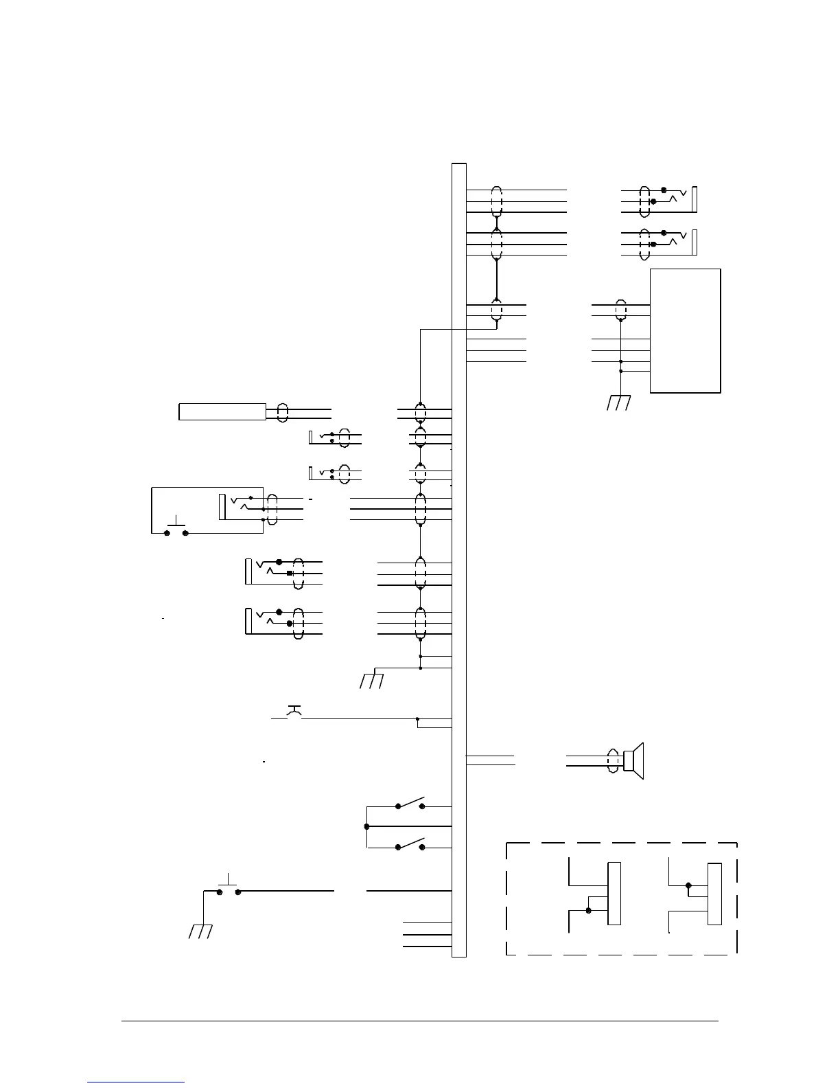
Appendix D – J2 Connector Interconnect
20
31
16
1
35
36
24
23
25
4
3
2
Copilot Phones (R)
Copilot Phones (L)
Copilot Phones Lo
Pass. 1 Mic Jack
Pass. Mic Lo
Pass. Mic Hi
37
38
Pass. 2 Mic Jack
Pass. Mic Lo
Pass. Mic Hi
32
33
34
Copilot Mic Audio
Copilot PTT
Copilot Mic Lo
Copi lot PT T
Copilot Mic Jack
14
13
Ent. #2 Mute
PAR200A J2 CONNECTOR
(Sub-D 44-pin male on tray)
Pass Music
27
26
28
Music #2 Audio (R)
Music #2 Audio (L)
Music #2 Audio Lo
Notes:
Music #1 Audio (R)
Music #1 Audio (L)
Music #1 Audio Lo
Crew Musi c
7
6
5
Copilot
Phones
Jack
Pilot Phones (R)
Pilot Phones (L)
Pilot Phones Lo
Pilot
Phones
Jack
Backlighting
See Sect. 2.4.2
8
9
Ground Lu g
A irframe Ground
11 -33 V DC
29
17
44
43
S wap
S wit ch
S wap
10
11
1. All Power, and Ground wires must be #22 g age wire
Lighting #22 AWG, other wires minimum #24 AWG.
TY91/92 Power and Ground shall be 20AWG.
2. All shields should be grounded at audio panel only,
other end remains floating
3. Pins 8 and 9 connected through a 3 A breaker
to aircraft power for the audio panel.
Breaker s must be pull-type.
4. All shielded wires must be MIL 22750 or 27500.
5. For music distri bution infor mation, see Section 2.5.1.
6. Use care when connecting music sig nal and ground inputs.
Failure to properly interface music can result in
added noise.
Do not connect M usic # 1 or Music #2 low
to g round. These are differential audio inputs.
Refer to 2.4.1.1.
7. Connecting J2-13 to ground (or J2-13 to J2-14)
will prevent the Music 2 input from
muting with intercom or radio.
8. Connecting J2-22 to ground (or J2-22 to J2-14)
places Muisc #1 in all headsets.
9. Pin 16 (pilot Phones Left) has COM 1 and
unswitched audi o in failsafe, and
must be connected to the tip contact,
and in a mono installation.
Unswitched Input #4 Hi
Unswitched Audio Lo
Unswitched Audio #4
15
40
7
6
5
28 V Lights Hi
28-Volt lights lo
7
6
5
14 V Lights Hi
14-Volt lights lo
See Note 7
3A B reaker
See Note 3
Backlighting
See Sect. 2.4.2
RS232 TXD
RS232 RXD
Com munic ation s
T ransc eiver
(T Y9 1/T Y92 -05 )
5
6
13
12
9
19
12
30
42
Radio On
Radio Power
Radio Ground
Speaker Hi
Speaker Lo
Cockpit Speaker
22
Music 1 All Headsets
See Note 8
See Note 6
(R) = Right Channel Audio
(L) = Left Channel Audio