PS Engineering Inc. ®
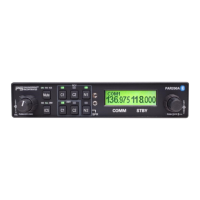
PAR200A Audio Selector Panel, COM radio Controller and Intercom System
Installation and Operator’s Manual
200-228-0200 Page 1-3 Rev. 4, DEC. 2017
Audio Selector Specifications
Audio selector panel input impedance:
4 (Com 1, Com 2, Nav 1, Nav 2)
38 mW each headset, no clipping <1% THD typical
into 150
Speaker Output (into 4 ) with no clipping
14 VDC:
28 VDC:
3 Watts (min.)
10 Watts (min.)
4 places (with individual IntelliVox® circuits) (8 with
expansion, -0202 ONLY)
>-30 dB "Soft Mute" when Com or intercom active.
<1% THD @ 38 mW into 150
Mic Freq. Response, 3 dB:
Music Freq. Response, 3 dB:
TY91L VHF Transceiver Specifications
Amplitude Modulation (AM) Aircraft Transceiver
Channels (Transmit & receive)
760 channels, 25KHz spacing
2280 channels, 8.33 kHz spacing
118.000 – 136.992MHz
Alpha/numeric LCD display (with backlighting) on
PAR200A
PLL frequency synthesis, which is microprocessor
controlled Memory is store in non-volatile EPROM
Power consumption Receive (no signal)
Transmit
11-33 VDC 5A Circuit Breaker.
5 watts (nominal) VSWR Tolerance < 2:1 for best
operation (5:1 without damage)
-6dB SINAD @ 5µV (1KHz audio with 70% modu-
lation)
Nominal 100 milliwatts output to 600 Ω
-20 to +70 degrees Celsius
W-2.5” x H-1.9” x D6.3” (plus 1.5” for harness) W-
66mm xH-48mm x D-160 (plus 35mm for har-
ness)