5
GENERAL OPERATION
BEFORE USE
1.
Check the hydraulic uid level,
following the instructions in the
Bleeding the pump section, if needed.
2. Determine which direction the frame
needs to be bent.
3. Remove any obstructions that could
be damaged or are in the way.
NOTE: When using the Pump (1) in a
vertical position, keep the hose end of
the Pump (3) downward.
4A. Using Ram:
a. Connect the appropriate Base
(9 or 13) to the stationary side
of the Ram (3), and connect the
appropriate head to the pushing end
of the Ram.
WARNING: Read and understand all the previous sections before use of this
product. Failure to comply with those sections may result in serious personal inju-
ry and/or property damage!
NOTE: When repairing larger body
panel dents such as a dented door,
fender or quarter-panel use the Rubber
Head (16) on the pushing end.
b. If using the Ram Toe (10) or Plunger
Toe (11): Thread the Ram Toe onto
the Ram completely and align the
Plunger Toe to it. The Ram Toe
and Plunger Toe must only be used
together to prevent off-center load.
Operation continued on page 6...
NOTE: During shipment or handling, air in the pump can become trapped in the
hydraulic system causing the pump to malfunction.
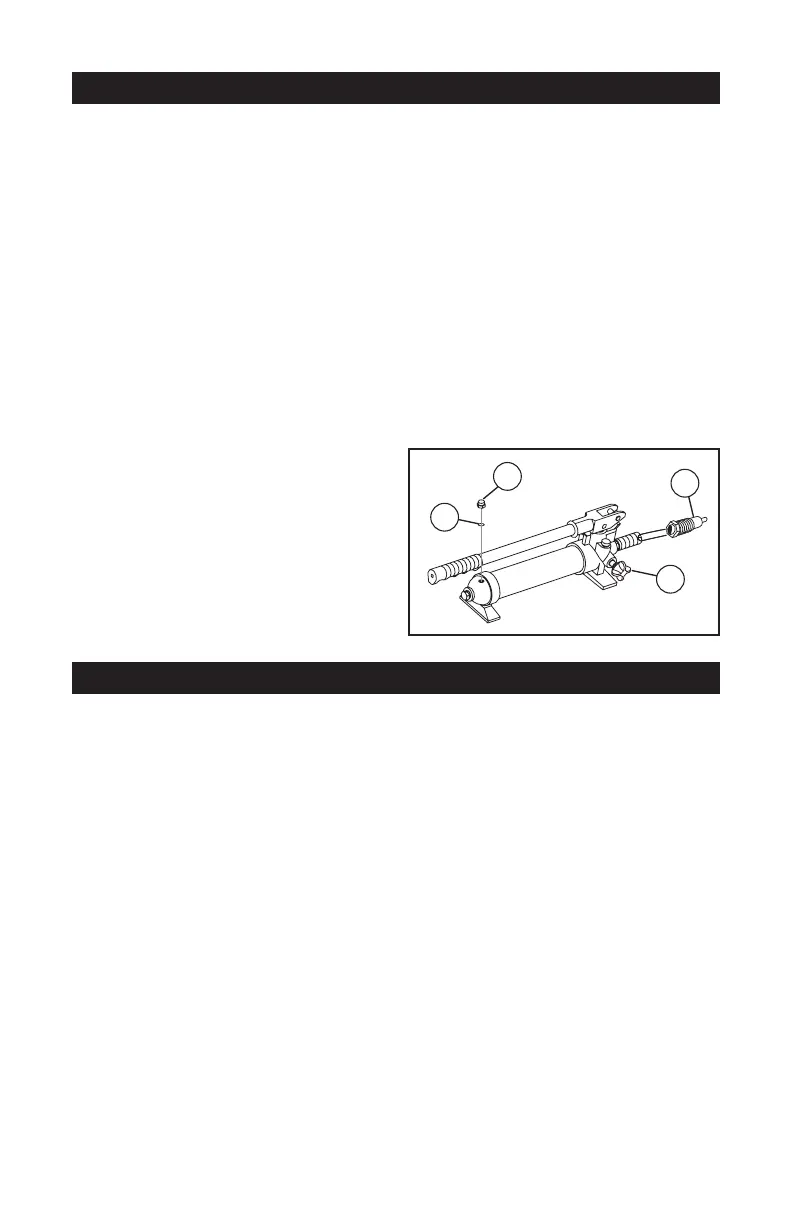
BLEEDING THE PUMP:
1. Set Pump (1) at on a level
surface.
2. Remove the Fill Screw (A). The
O-ring (B) should come off with it.
3. The uid level should be near the
bottom of the opening. If required,
add high grade hydraulic uid.
4. Make sure the O-ring (B) is still in
place around the Fill Screw (A) and
thread the Fill Screw into the Pump
securely. Do not use thread seal
tape.
5. Firmly close the Release Valve (C)
by turning it clockwise.
6. Press the tip of the Coupling (D)
against a hard surface and pump
the pump handle.
7.
Continue pumping, until the
hydraulic uid coming out the end of
the coupler tip is free of air bubbles.
A
B
C
D
Fig. 4
8. Recheck the uid level and add
uid if necessary.
9. Turn the Release Valve counter-
clockwise to release the pressure
in the pump and hose.
10. Change the hydraulic uid yearly.
Remove the Fill Screw (A) and tilt
the Pump (1) to drain out the old
uid. Rell the hydraulic uid and
bleed the system several times to
ensure all air is out of the system.