11984 Rev 01 Page 7 of 8
1.3 Requirements
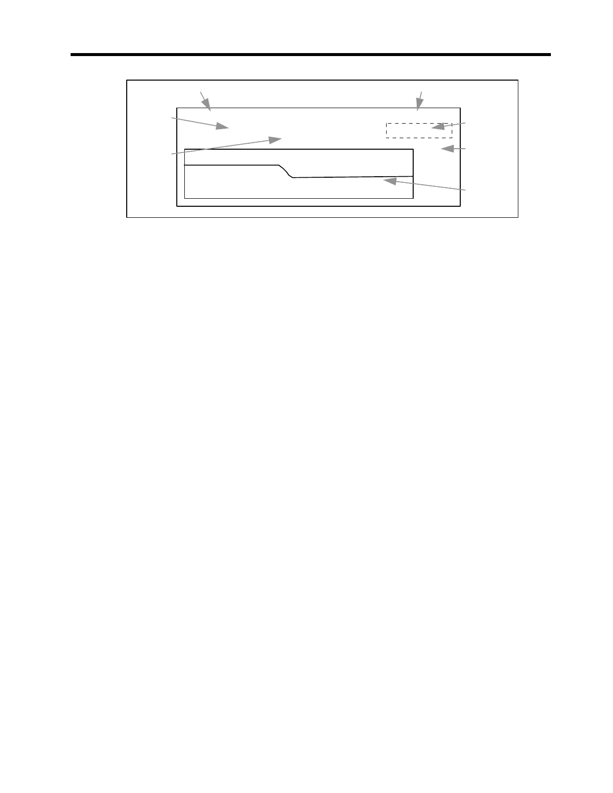
Sentry Ver G1.9
SUN 00:00:00
Pres S 1700 Pres 1700
FLOW
2000
0
Software version Day - Time
Alarm
Display
Full Scale
2.000"
Real time
trend
Setpoint
Measured
pressure
Figure 1-4: The Supervisor LCD Display gives the user a “window on to the
process.”
The Supervisor acts as the interface and display between the user and the
SENTRY 1510. The Supervisor has a graphic display screen that provides the
operator information about the SENTRY and the process. This includes the set
point, measured process exhaust pressure, alarm status and the date and time
(see Figure 1-4). The pressure information is displayed in real time and in
graphical form. A 4-key interface allows the operator to control the SENTRY 1510
in local mode. In local mode, the operator can key in set point changes and modify
control parameters. For more information on the Supervisor, refer to the “SENTRY
Supervisor Operation Manual and Serial Communications Programmer’s Guide”.
There are two options for supplying power to the Supervisor: from the “host” or
stand alone.
1. In the stand-alone configuration, the Supervisor is fitted with a power adapter
cable. The adapter cable includes a standard AC wall plug and power supply
that generates two DC operating voltages. (NOTE: Power supplies are avail-
able for several AC voltages. Check the voltage marked on the cable for
compatibility with your installation.) The interface cable mates the power
supply to the Supervisor.
2. The second option allows power to be supplied directly from the process tool
controller eliminating the need for an AC supply. In this case, the host interface
cable carries positive and negative DC power to the Supervisor. The DC
requirements are:
+ 15 to 24 VDC at 500 mA
-15 to -24 VDC at 50 mA
There are two options for communications with a host (typically the process tool
controller): “serial” and “analog”