Press simultaneously and hold for two seconds buttons “LEFT” (10) and
”MODE” (12) or RC buttons (23) and (24) to enter the auxiliary menu.
Press buttons “LEFT” (10) or “RIGHT”(11) to select menu item
“Display calibration”. Press “MODE” to confirm.
Press and hold down the “MODE” (12) button for two seconds to enter the
menu.
Press briefly navigation buttons - “LEFT” (10) and “RIGHT” (11) to select
icon , press “MODE”.
Select icon in the pop-up submenu and press “MODE”.
If you wish to return to the default defective pixel pattern (i.e. restore all
defective pixels previously repaired), select icon in the pop-up submenu and
press the “MODE” button.
Options “Yes” and “No” appear on the right of the “MODE” button.
Use navigation buttons to select “Yes” and press the “MODE” button.
If you choose not to return to default pixel pattern, select “No” and press
“MODE” button.
To exit the main menu, press and hold down the “MODE” button for two
seconds or wait 10 seconds to exit automatically.
Attention! One or two pixels in the form of bright white or black 1-2 pixels
dots are allowed on the display of thermal imager. These pixels cannot be
repaired and are not a defect.
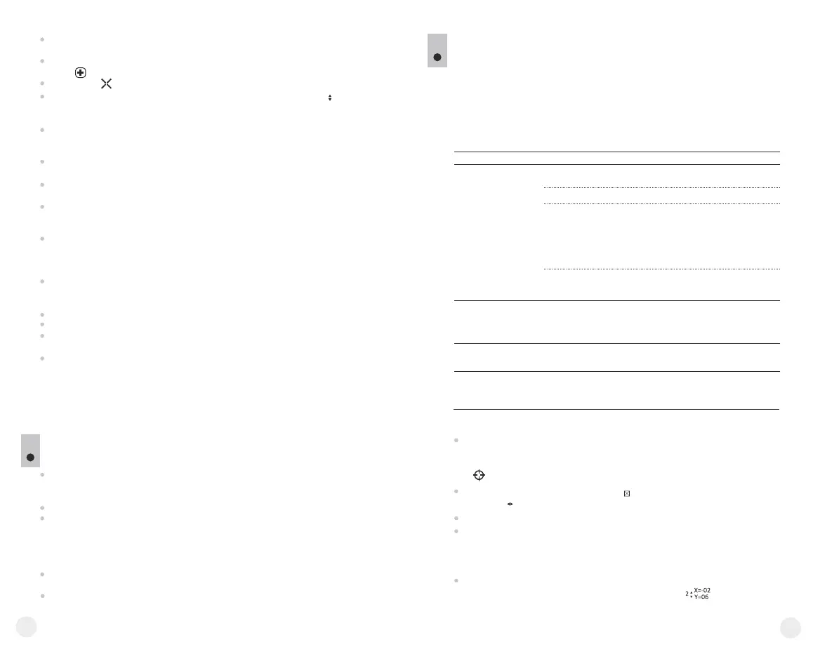
A red cross appears in the centre of display, coordinates (X; Y) of the
cross relative to the centre of display appear in the place of pop-up icons,
icons disappear.
Use navigation buttons to align the center of the cross with a defective pixel
(defective pixel should go out). Switch direction of the cross from horizontal
to vertical by a short press of the “MODE” button.
After the centre of the cross is aligned with a defective pixel, press the
“ON/OFF” (9) button to repair the pixel.
In case of success a short “OK” message appears next to the coordinates.
Further on, move the cross to repair another defective pixel. When moving
the cross to the coordinates area, the latter goes to the lower right portion of
the display.
To exit menu option “Defective pixel repair”, press and hold button
“MODE” for two seconds.
Return to default defective pixel pattern
X=50
Y=50
14
MAINTENANCE AND STORAGE
12
The unit in monocular mode features degree of protection IPX7 (fully
waterproof, submersible at 1 meter for 30 minutes); in attachment mode
IPX5 - protection against water jets.
Attempts to disassemble or repair the scope will void the warranty!
Clean the scope's optical surfaces only if necessary, and use caution. First,
remove (by blowing with a blower brush or canned air) any dust or sand
particles. Then proceed to clean by using camera/lens cleaning equipment
approved for use with multicoated lenses. Do not pour the solution directly
onto the lens!
Always store the unit in its carrying case in a dry, well-ventilated space. For
prolonged storage, remove the batteries.
Batteries shall not be exposed to excessive heat such as sunshine, fire or the
like.
15
13
TROUBLESHOOTING
Listed below are some potential problems that may occur when using the
scope. Carry out the recommended checks and troubleshooting steps in the
order listed. Please note that the table does not list all of the possible
problems. If the problem experienced with the scope is not listed, or if the
suggested action meant to correct it does not resolve the problem, please
contact the manufacturer.
Problem
Possible cause Corrective action
The unit will not turn on.
The image is blurry, with
vertical stripes and uneven
background.
Batteries have been
incorrectly installed.
Oxidized contact points in the
battery compartment or
on the battery cover due to
“leaky” batteries or contact
points becoming exposed
to a chemically reactive solution.
The batteries are fully
exhausted or one or
several batteries are faulty.
Calibration is to be done.
Reinstall the batteries
observing polarity.
Clean the contacts of the battery
compartment or the battery cover.
Install fresh batteries.
Do the calibration according
to section 9 “OPERATION”
The image is too dark.
The lowest brightness level
is set.
Adjust display brightness.
Point of impact does not
match the aiming point.
Display calibration needs to be
done.
Do display calibration as per
guidelines below.
Battery cover is not tightly closed. Close tightly the battery cover.
Display calibration
Auxiliary cross in a limiting frame and symbols will appear on the
display .
First, match the auxiliary cross and the centre of sight’s reticle.
To move the frame with the cross horizontally and vertically, press buttons
“LEFT” or “RIGHT” (or RC buttons (22),(24)). Movement takes places
upon both short and long press. To switch movement direction from
horizontal to vertical, press button “MODE” or (23) RC button.
Second, hold “MODE” (or (23) RC button) for two seconds. Figure “2”
and X, Y coordinates values appear next to the icon .
1
 Loading...