ENGLISH
Ring Adapter
model
The internal diameter of the insert needs to match the outer diameter of the
objective lens housing of the daylight riescope it is being installed on.
Insert internal diameter, mm
Suitable for lens housing of daylight riescopes
with an outer diameter of, mm
PSP Ring
Adapter 42 mm
45.5 45.5
46 46
46.5 46.5
47 46.7-47.6
48 47.7- 48.6
49 48.7-49.6
50 49.7-50.6
PSP Ring
Adapter 50 mm
51.6 51.6
53.4 53.4
55 54.7-55.6
56 55.7-56.6
57 56.7-57.6
58 57.7-58.6
59 58.7-59.6
PSP Ring
Adapter 56 mm
60 59.7-60.6
61 60.7-61.6
62 61.7-62.6
63 62.7-63.6
64 63.7-64.6
65 64.7-65.6
•
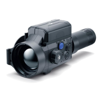
Screw together the Ring Adapter (15) and the attachment along the threads
of the mounting area (20) until it stops. Then untighten a little (no more than
one turn) so that the lever (19) is on the right side (see Figure).
•
Evenly tighten the screws (16) until the ball joint grips in the Ring Adapter (15).
•
Apply 2-3 strips of double-sided tape to the outer surface of the insert of
your choice (14).
•
Push the insert (14) of your choice into the Ring Adapter (15) until it stops.
•
Move the lever (19) to the OPEN position.
•
Before installing the Ring Adapter (15) onto the optical sight, it is
recommended to degrease the lens body of the optical sight (13).
•
Mount the Ring Adapter (15) with the insert (14) onto the lens of the optical
sight (13) as far as it will go.
•
If the Ring Adaptor (15) with the insert (14) selected according to the table
cannot be mounted onto the lens (10), follow the steps below:
- Loosen the locking screw (17) with a 2mm Allen key.
- Untighten the screw (18) with a hex wrench (S = 4mm) until the Ring
Adaptor with the insert can be mounted onto the lens (13).
•
Move the lever (19) from its initial OPEN position to the CLOSE position.
•
Loosen the locking screw (17) with a 2mm Allen key, if it hasn’t been done before.
•
Tighten the screw (18) using a 4mm Allen key. The clamping force should be
1.5-2 Nm (use a torque screwdriver) to ensure the lever is correctly tightened
(19), while the Ring Adapter with the attachment should not move relative
to the body of the optical sight (13). If necessary, tighten or loosen the screw
(18) to operate the lever (19) in the best way possible.
•
Tighten the locking screw (17) as far as it will go.
•
Turn on the attachment by briey pressing the ON button (9).
•
Align the display center with the crosshairs of the reticle by tilting the
attachment.
4
 Loading...