13
4TOLB-3L1
1306, Issue 2, May 1992
STEP ACTION
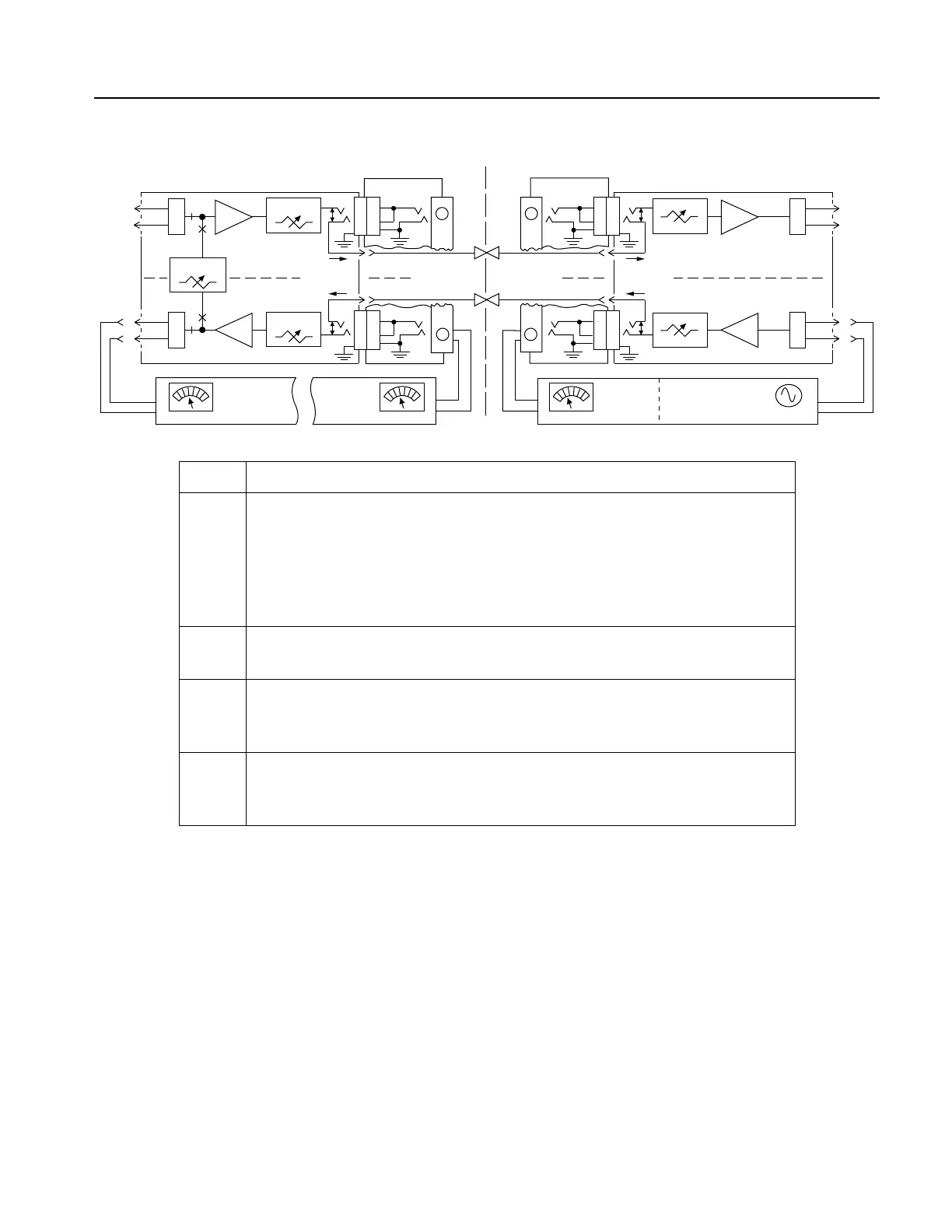
1 Arrange with the far end to set the TMS2 in the bridged mode and to adjust
the TMS2 oscillator output for a 1004-Hz tone at the desired TRMT input
level (between +16 dB and –16 dB TLP). Also arrange to connect the
oscillator to the TRMT IN port (connector pins 24 and 51) and the level meter
to the TX TLP port (jack J2–TX TLP of the MAC Jack to Bantam Jack
Adapter).
2 A level meter reading of –8.5
±
0.25 dBm can be achieved by varying the
far-end TRMT attenuation.
3 In the near end set the TMS1 in the bridged mode and connect the TMS1
level meter to the RX TLP port (jack J2–RX TLP of the MAC Jack to Bantam
Jack Adapter). Verify a meter reading of +4.0
±
0.25 dBm.
4 Move the TMS1 level meter to the RCV OUT port (connector pins 20 and 47)
and set the TMS1 in the terminated mode. Vary the RCV attenuation switches
to attain the desired near-end RCV output.
B. Near-End RCV and Far-End TRMT Alignment
Figure 7. TRMT, RCV, and LB Alignment Procedures and Test Equipment Setups (Continued)
MAC TO BANTAM
ADAPTER
NEAR
END
X
F
M
R
9
1
7
3
0 to 32.5 dB
0 to 24 dB
T1
R1
TRANSMIT PATH
RECEIVE PATH
B
P/O
J2
MODEL 4TOLB-3L1 UNDER TEST
P/O J1
P/O P1
MAC TO BANTAM
ADAPTER
FAR
END
7
3
9
1
P/O J1
P/O P1
TRANSMIT PATH
RECEIVE PATH
+7.5
dB
A
P/O
J2
P/O J1
P/O P1
TO/FROM
CHAN. BANK
P/O
J2
P/O J1
P/O P1
B
P/O
J2
TO/FROM
CHAN. BANK
T
R
-8.5
±0.25
dBM
OSCILLATOR
1004 Hz
(+16 dB to -16 dB TLP)
TMS 2
(BRIDGED MODE)
LEVEL METER
TX
TLP
TRMT
IN
24
51
+3
dB
+4.0
±0.25
dBM
DESIRED
RCV TLP
OUT
P/O TMS 1
(BRIDGED MODE)
T1
R1
RX
TLP
LEVEL METERLEVEL METER
P/O TMS 1
(TERMINATED MODE)
RCV
OUT
47
20
T
R
A
X
F
M
R
X
F
M
R
X
F
M
R
0 to ±31.75 dB
LB
LB