4TOLB-3L1
1306, Issue 2, May 1992
14
STEP ACTION
1 Arrange with the far end to set the TMS2 in the bridged mode. Also arrange to
adjust the TMS2 oscillator output to the same frequency and level used in
Step B-1, to connect the TMS2 oscillator to the TRMT IN port (connector
pins 24 and 51), and to connect the TMS2 level meter to the RCV OUT port
(connector pins 20 and 47).
2 In the near end set the loopback attenuation switches OUT and the gain/loss
setting to LOSS.
3 Activate the near-end LB circuit either by setting the front-panel LB switch
ON or by arranging with the far end to inject a 2713-Hz tone of proper level
(0 to –30 dBm0) and duration (> 2.5 seconds).
4 Request the far end to observe whether the TMS2 level meter reading is
higher or lower than it was in Step A-5.
A) If the level is higher, leave the gain/loss setting on LOSS.
B) If the level is lower, set the gain/loss selection to GAIN.
5 Vary the loopback attenuation settings on the near end to achieve the same
RCV OUT level that was attained in Step B-4.
6 Unloop the near-end unit.
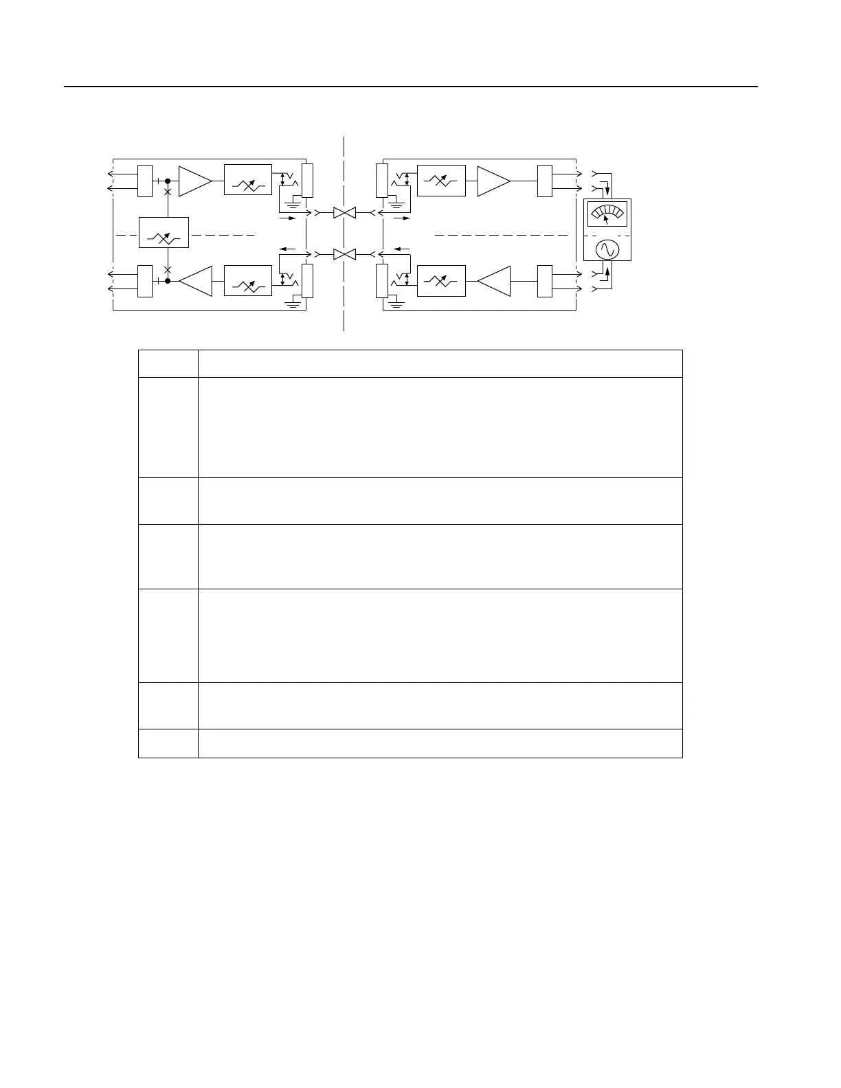
C. Loopback Alignment
Figure 7. TRMT, RCV, and LB Alignment Procedures and Test Equipment Setups (Continued)
NEAR
END
FAR
END
0 to 32.5 dB
0 to 24 dB
T1
R1
MODEL 4TOLB-3L1 UNDER TEST
(LOOPBACK MODE ENABLED)
7
3
9
1
P/O J1
TRANSMIT PATH
RECEIVE PATH
+7.5
dB
P/O J1
TO/FROM
CHAN. BANK
T
R
+3
dB
X
F
M
R
X
F
M
R
0 to ±31.75 dB
LB
LB
X
F
M
R
9
1
7
3
TRANSMIT PATH
RECEIVE PATH
P/O J1P/O J1
TO/FROM
CHAN. BANK
T1
R1
T
R
X
F
M
R
TMS-2
47
20
24
51
TRMT
IN
BRIDGED
MODE
1004 Hz
(+16 dB to
-16 dB TLP)
NOTE: RCV TLP OUT MUST
BE SAME AS NEAR END RCV
OUT LEVEL IN TEST PART B.
DESIRED
RCV TLP
OUT