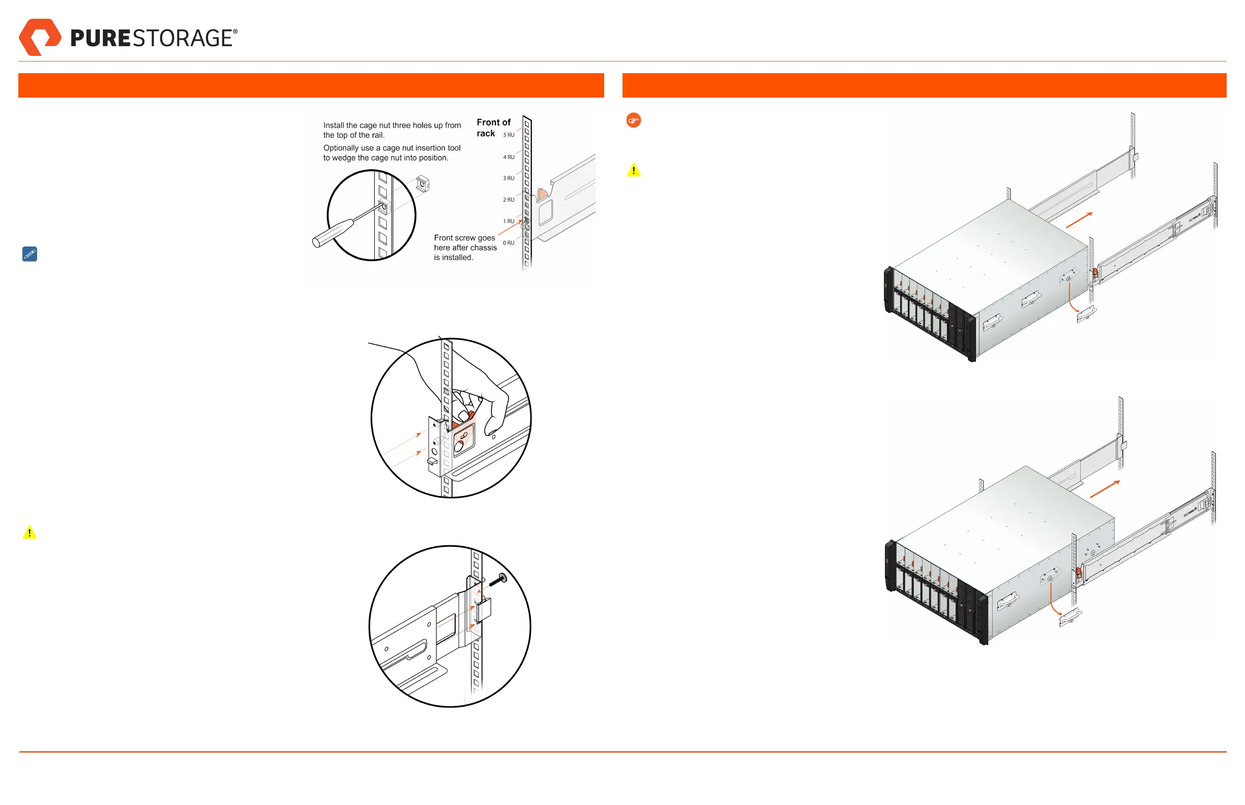
2. Install the Rails
The chassis includes two rails, labeled right and left. The
rails have locating pins (for square- and round-hole
racks) or positioning studs (visible if you unscrew and
remove the locating pins for threaded-hole racks) that
align with the holes in the rack.
1. (Square-hole racks only) Install the #10-32 cage
nuts (included in Rail Kit) on the back side of the
front rack post, as shown in Figure 2. The cage nut
insertion tool is not provided.
For round-hole racks, use clip nuts (not provided)
instead of cage nuts.
2. Install one of the two rails (the installation order does
not matter) by pulling the spring-loaded lever back
and inserting the locating pins or positioning studs in
the front mounting post at the desired height.
Release the lever once the rail is in place. See Fig-
ure 3.
3. Extend the rear of the rail until the locating pins or
positioning studs reach the rear mounting post, and
press the rail into the rear post until the latch
engages. See Figure 4 (left rail shown).
4. (All rack types) Secure the rear of each rail to the
rack with the screws provided in the Rail Kit. One
screw is provided for the rear of each rail. Use the
second or fifth hole up from the bottom of each rail
(shown going into the fifth hole). See Figure 4.
5. Repeat the previous steps to install the second rail.
Make sure to install the rear of each rail into the post
holes that are at the same height as the holes being
used on the front post. Otherwise, the chassis might
slide off the rails causing personal injury and dam-
age to the chassis.
Figure 2. Installing Cage Nuts
Figure 3. Installing a Rail (Front Post)
Figure 4. Installing a Rail (Rear Post)
3. Mount the Chassis into the Rack
Remove the clear protective film on the top sur-
face of the chassis before installing into the
rack.
To avoid injury or damage to the system, do
not insert hands or fingers into the empty drive
bays.
1. Use a mechanical lift to raise the chassis to the
desired height in the rack.
2. Set the rear of the chassis onto the rails and
remove the rear handles while using the mech-
anical lift to support the front of the chassis.
To remove a handle, pull the plunger and slide
it downward. See Figure 5.
3. Continue to slide the chassis into the rack until
you have a two-inch gap between the middle
handles and the rack.
Remove the middle handles while using the
mechanical lift to support the front of the
chassis. See Figure 6.
Figure 5. Mounting to Rack (Part 1)
Figure 6. Mounting to Rack (Part 2)
FlashBlade//S Quick Installation Guide
PN: 40-0284-00 Page 2 of 5 March 25, 2022
 Loading...