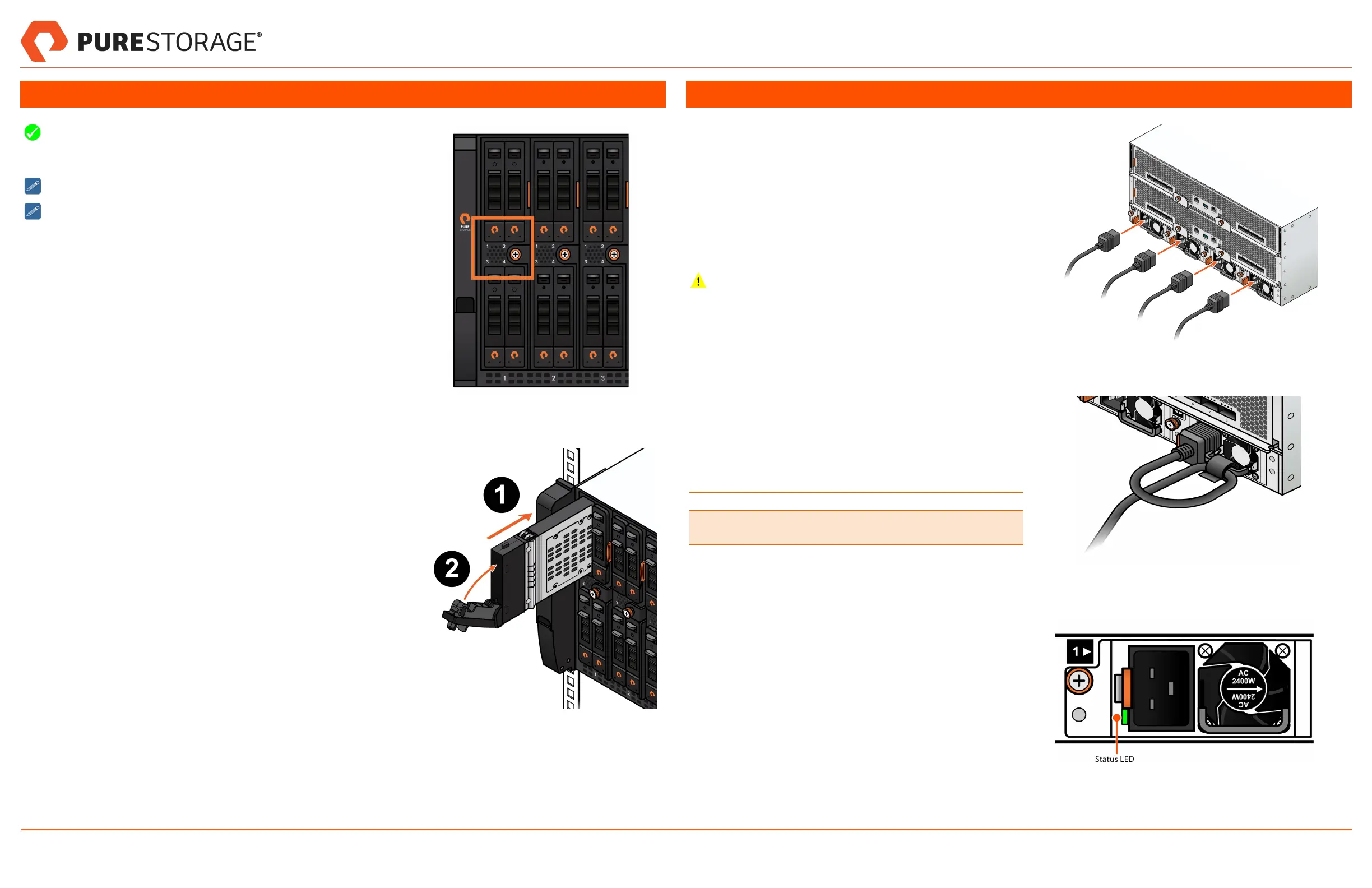
5. Install DirectFlash Modules
DirectFlash Modules (DFM) must be installed into the slot in sequen-
tial order (1-2-3-4). Each blade must have the same number of DFMs
installed. See Figure 11.
Locate the boxes with DFMs and prepare for installation.
Make sure all unused slots are filled with blanks.
Working with one DFM box at a time:
1. Open the front latch on the drive fully, then slide the DFM into the slot
and close the latch as you seat the module. See Figure 12.
2. Continue populating the remaining slots with the DFMs in the box, 1
per blade.
3. Make sure the drive module front panels are flush with the chassis
front panel. Check the latch on each module is engaged by pulling
gently on it until you feel resistance.
4. Repeat the previous steps for the remaining boxes of DFMs.
5. Install drive blanks in any unused drive slots to ensure adequate air-
flow. The drive blanks do not have a latching mechanism.
6. (Optional) Use the Torx T10 screw driver included in the Accessory
Kit box to lock each DFM into its blade slot.
Figure 11. DFM Slot Numbers
Figure 12. Inserting the DFM
6. Power on the System
1. Connect power cords to the chassis power supply units
(PSU) starting with PSU1 and proceeding through PSU4.
See Figure 13.
l Lift the power supply handle, make a loop in the
power cord nearest to the plug, wrap the captive
strap around the loop, and secure the cord to the
handle. See Figure 14.
l Insert the power plug into the power supply socket.
Secure the power cords to the power supply handles with
captive straps to prevent accidental disconnections.
2. Connect the PSU1 and PSU2 power cords to an AC
power distribution unit. After connecting the power, the
Fabric I/O Module (FIOM) LEDs illuminate and the fans
begin to spin up.
3. Connect the PSU3 and PSU4 power cords to a separate
AC power distribution unit for redundancy.
4. Check the status of each PSU after connecting all the
power cords. See Figure 15 and Table 1 for LED status
information.
Table 1. Power Supply Unit Status LED
LED Status Description
PSU status (on each PSU) Green if OK. Amber
if faulty.
Figure 13. Connecting Power Cords
Figure 14. Securing the Cord
Figure 15. PSU Status LED
FlashBlade//S Quick Installation Guide
PN: 40-0284-00 Page 4 of 5 March 25, 2022