EasyManua.ls Logo

Purkeys 1200+ - User Manual

Purkeys 1200+
18 pages
Print Icon
To Next Page IconTo Next Page
Loading...
1200+ WITH TIMER
V1.00
OWNERS MANUAL

Questions and Answers

  • J
    Jamie SanchezJul 31, 2025
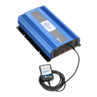
    Why Purkeys 1200+ Inverter has no AC output, Yellow LED is lit and Green LED is not lit?
    • M
      Marc WagnerJul 31, 2025
      If your Purkeys Inverter isn't providing AC output, the yellow LED is lit, and the green LED isn't lit, it could be due to the DC input being below 10.5 volts. Test the batteries and perform a voltage drop test. Also, inspect the vehicle's charging system.
  • D
    Desiree CastilloAug 4, 2025
    What to do if Purkeys Inverter low battery alarm sounds abnormal?
    • M
      Margaret SnyderAug 4, 2025
      If your Purkeys Inverter's low battery alarm sounds abnormal, there may be a bad connection or wiring issues. Conduct a voltage drop test, and repair or replace any faulty components as needed.
  • C
    Cynthia RichardsAug 8, 2025
    Why motorized power tool does not operate at correct speed with Purkeys 1200+?
    • Y
      ygonzalezAug 8, 2025
      If a motorized power tool isn't operating at the correct speed with your Purkeys Inverter, it might be due to a purely inductive load. To resolve this, make the load not purely inductive by operating an incandescent lamp at the same time as the motor.
  • C
    Christina LopezAug 13, 2025
    Why does Purkeys Inverter low battery alarm sound?
    • R
      Rodney DuncanAug 13, 2025
      If your Purkeys Inverter's low battery alarm is sounding, it is likely due to low battery voltage. Recharge or replace the batteries. Also, check the vehicle charging system.
  • A
    Alison WeissAug 17, 2025
    Why Purkeys 1200+ Inverter has Yellow LED lit when power is on?
    • J
      James SanchezAug 17, 2025
      If your Purkeys Inverter has the yellow LED lit when the power is on, it indicates weak batteries or cable issues. Test the batteries and conduct a voltage drop test.
  • J
    Jacob WatsonAug 21, 2025
    Why motorized power tool won't start with Purkeys Inverter?
    • R
      Robert WyattAug 21, 2025
      If a motorized power tool won't start with your Purkeys Inverter, it's likely due to an excessive start-up load. If the appliance doesn't start, it's drawing too much wattage and won't work with this inverter. Check with a Kill-a-Watt tester.
  • D
    Derek KruegerAug 26, 2025
    Why Purkeys Inverter red LED light turns off and on and the on/off switch is on?
    • C
      Carly MorseAug 26, 2025
      If the red LED light on your Purkeys Inverter turns off and on while the on/off switch is on, the timer has timed out because the inverter has been used for the entire run time during the set period. You must wait until the remaining time of the set period expires or reset the timer.

Summary

General Information

Important Safety Instructions

Key safety advice for proper installation and use to prevent damage and injury.

Warnings

Critical safety warnings regarding fire, shock, explosion, and misuse of the inverter.

Cautions

Important cautions concerning system type, appliance limits, environment, and medical device use.

Introduction and Technology

Cable Information

Guidance on cable selection and connections for optimal power and battery life.

Key Technologies

Explains UP-Circuit, L.I.T., and Soft Start circuits for improved performance.

Protective Features

Over Temperature Protection

Automatic shutdown when internal temperature is too high; requires cooling.

Voltage and Load Protections

Covers Low/Over Voltage, Overload, Short Circuit, and Earth Fault protections.

Low Battery Alarm and Waveform

Details alarm for low battery and explains the Modified/Quasi sine wave output.

Operating Environment

Placement Criteria

Guidelines for placing the inverter on a flat surface in dry, cool, ventilated, and safe locations.

Mounting Guidelines

Recommendations for horizontal wall mounting to ensure visibility and accessibility of controls.

Inverter Features

Top LED Indicators

Top LEDs indicate Timer Functions for the inverter's operation.

Mini DIN Connector

Used for programming and timing out the inverter's functions.

Bottom LED Indicators

Bottom three LEDs (red, yellow, green) display inverter operational status.

Installation Instructions

Vehicle Specific Harnesses

Custom harnesses with vehicle-specific instructions for unique installation environments.

General Layout Diagram

Diagram illustrating the internal and external cab area connections for the inverter.

Wiring Harness Kit

Visual representation of the components included in the wiring harness kit.

Cable Connections

Chassis Ground Cable

Connects inverter chassis to grounding point for fault current path and protection.

Remote Sense Stud

R-Terminal used to determine if the vehicle engine is running or off.

Inverter Troubleshooting

DC Input Power Issues

Troubleshooting guide for common DC input problems and suggested remedies.

AC Output Power Issues

Troubleshooting guide for common AC output problems and suggested remedies.

Inverter Troubleshooting Continued

Timer Controlled Unit Issues

Troubleshooting for LED indications related to the timer function and unit status.

Inverter Voltage Drop Test

Test Procedure

Step-by-step guide to testing voltage drop using the Auto Meter BCT-200J tester.

Test Specifications

Details the acceptable total voltage drop limit (.396) for the complete circuit.

Kill-A-Watt Operation

Meter Readings and Buttons

Explains LCD readings (Volts, Amps, Watts, etc.) and button functions on the Kill-A-Watt meter.

KWH;Hour Button Function

Describes toggling between cumulative energy consumption (KWH) and time (Hour).

Inverter Tool Instructions

Resetting the Inverter

Procedure for resetting the inverter when the red LED is flashing.

Inverter Reset Procedure

Disconnect Power

Disconnect the positive lead from the battery box fuse cube to remove power.

Drain Capacitors

Short out power inputs using a special tool to drain internal inverter capacitors.

Remove Drain Tool

Remove the capacitor drain tool after draining the internal capacitors.

Inverter Reset Completion

Insert Reset Adapter

Insert the resetting adapter tool into the inverter's mini-din connector.

Reconnect Power and Test

Reconnect power, turn on, wait for LEDs, detach adapter, and power cycle.

Limited Commercial Warranty Policy

Warranty Coverage and Period

Details warranty for defects in material/workmanship for 24 months from in-service date.

Warranty Exclusions

Lists conditions under which the warranty is void, including misuse, accident, or improper installation.

Warranty Claim Process

Outlines requirements for submitting a warranty claim, including form completion and part submission.

Warranty Disclaimer

Limitation of Damages

Purkeys disclaims liability for incidental, consequential, or other damages arising from product use.

Other Warranties Disclaimed

This limited warranty supersedes all other express or implied warranties, including merchantability.

Purkeys 1200+ Specifications

General IconGeneral
BrandPurkeys
Model1200+
CategoryInverter
LanguageEnglish

Related product manuals