21
conductor from array 1 is connected with wires in array 2. An example is if inverter
A has the positive conductor from array 1 and the negative conductor from array 2 con-
nected.
If the fuse is blown or open, then a ground fault condition exists. 4.
Check the DC voltage between the grounded terminal of the array and earth ground.•
The voltage should be less than 25 VDC with the GFI fuse removed. If the voltage is s
greater than this, check the array wiring as there may be a ground fault. For the best
results, perform this test with the PV System Disconnect on and off. If you are not
comfortable conducting this test, DO NOT ATTEMPT IT. (See PV System Discon-
nect, Installation and Operations Manual for AC and DC disconnect information).
If a ground fault condition is not present because it is now repaired or intermittent, •
replace the fuse with a similar fuse rated at 600VDC and 1A.
Make sure the grounded leg of the PV array is not broken in the PV System Disconnect.5.
Note: The GFI is a latching circuit which prevents the inverter from operating until the
fault is repaired and the inverter is reset. The inverter will not operate, even if the
fault is repaired, unless it is manually reset by turning the AC source circuit off
and then on.
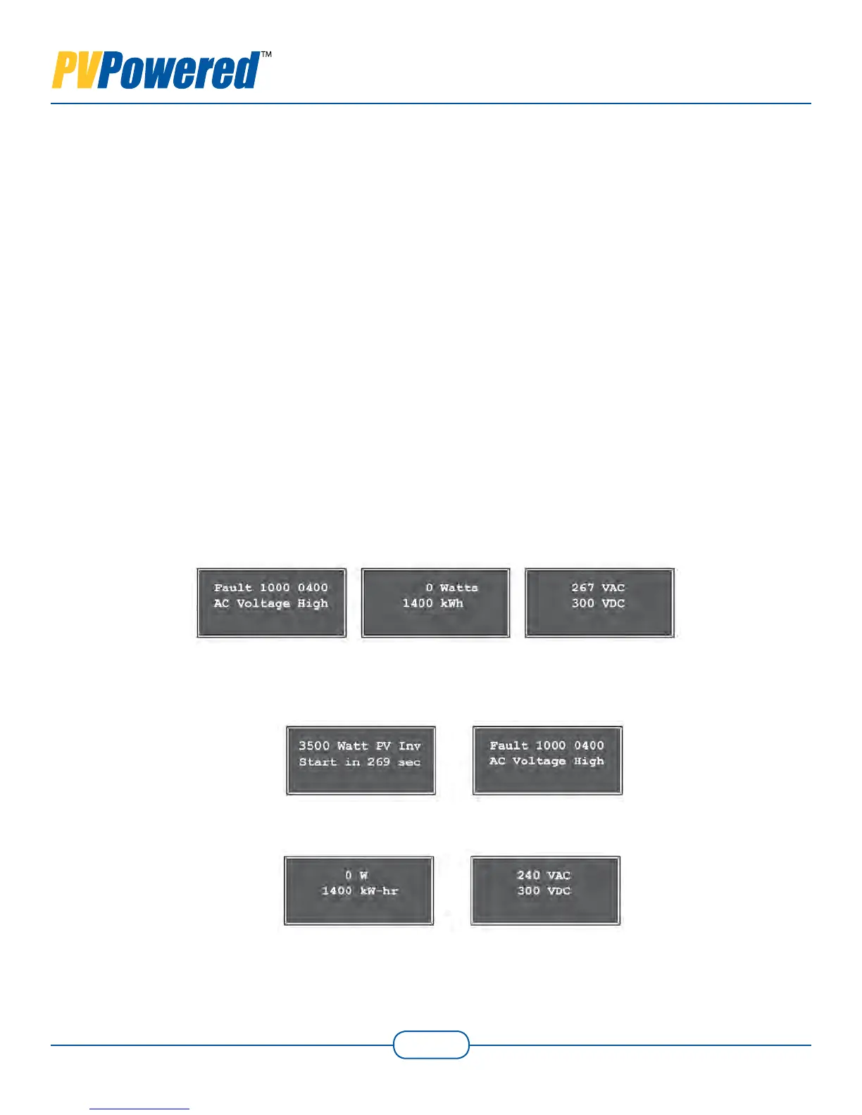
Displayed Fault Codes5.2
The vacuum fluorescent display (VFD) provides the codes shown in Figures 5-1 and 5-2
when a fault has occurred.
Screen 1 Screen 2 Screen 3
Figure 5-1 Faulted
Screen 1 Screen 2
Screen 1 Screen 2
Figure 5-2 Starting Up From a Faulted State