Rins141 Issue 7 Page 11
9 POWER CONNECTIONS
9.1 Low Voltage a.c. Connections
The Atlas 4 requires a supply of 17V a.c. from the power supply unit or transformer, with a current capacity of 1 amp.
Connect the 17V current to the terminals marked 17~ on the PCB.
9.2 Battery Connection
+BAT-
B+ BA Z1
In order for the Atlas 4 to operate if the mains power is cut a battery back-up is required. Refer to 9.6 for battery
specifications. Connect the battery to the terminals marked +BAT- on the PCB.
9.3 Bell and Strobe
The bell Negative (-) should be returned to the BAT (-) connection on the PCB.
The bell tamper must be connected to a tamper zone or connected as end of line zone. Bell box strobe connections
should be linked together at the bell box.
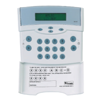
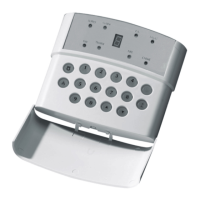
9.4 Remote Keypad ‘RKP’ Connections
If more than one keypad is to be used, additional keypads can be wired in either daisy chain or star configuration.
The RKP tamper must be connected to a tamper zone or connected as end of line zone.
9.5 Programmable Output "PGM" Connections
The Programmable Output is switched negative (-) on activation.
17V a.c.
To Battery Positive (+)
To Batter
Ne
ative
-
+BAT-
B+ BA Z1 Z2 Z3 Z4 -AUX+ KD PR1
Bell Trigger
Bell Positive (+)
+BAT-
B+ BA Z1 Z2 Z3 Z4 -AUX+ KD PR1
Keypad Data
Keypad Negative (-)
Keypad Positive (+)
+BAT-
B+ BA Z1 Z2 Z3 Z4 -AUX+ KD PR1
Programmable Output
17V~
 Loading...