Rins141 Issue 7 Page 5
1 INTRODUCTION
The Atlas 4 is a fully featured uploading / downloading intruder alarm control panel, based around a micro-controller with4 fully
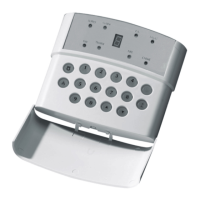
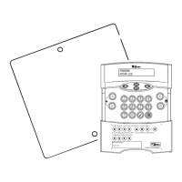
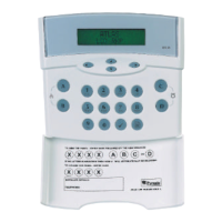
programmable zones. It may be operated via a single Remote Keypad, a maximum of 3 remote keypads (Atlas RKP’s) may be
fitted at convenient points around the premises. Each keypad has an arrangement of 8 LED’s to show the status of the system,
and a 7-segment display to show programming data and events held in the event-log memory.
All features are fully programmable and there are three levels of access to the system.
The Limited User codes allow access to the basic functions needed for everyday setting and unsetting of the system.
The Master User level gives access to all setting and unsetting facilities, but also allows the changing of code numbers
and testing of the system.
The Engineer level gives total access to the system including the ability to reconfigure the system and reset the system
event-log memory. The Engineer cannot, however, set or unset the system.
NOTE: The Atlas 4 uses the same software to control the panel as the Atlas 8, therefore any programming of zones will
show all 8 zones, however only the first 4 are available for use.
2 SAFETY
The 17V a.c. supply to the control panel is connected into the PCB terminal blocks marked 17~. Signal wires to
detectors, etc., should be securely tied together on completion of the installation, to prevent the possibility of a safety
hazard in the event of a wire becoming loose.
NOTE: This equipment is not suitable for location in bathrooms or damp conditions.
3 ACCESS LEVELS
3.1 Limited User Level Enables: Panel setting and unsetting with a unique pass code.
1. Setting and unsetting of the door chime facility.
2. Event log viewing.
3.2 Master User Level Enables: All Limited User facilities.
3. Clearing of event log (if allowed by the Engineer).
4. Alteration of both Limited and Master User codes.
5. LED and Bell test facility.
6. Walk test facility for all four set modes.
7. Programmable output operations.
8. Remote Dial in enabling.
3.3 Engineer Level Enables: a. All Master User facilities except setting and unsetting.
b. Zone programming for all four set modes.
c. Bell timer setting.
d. Entry / Exit timer settings.
e. Alteration of Engineer code.
f. Enabling or Disabling of Event log reset by Master user.
g. Programming of communication and programmable output options.
4 FUNCTIONAL DESCRIPTION
4.1 Operating Modes
Day Mode This is the state of the panel when unset. Fire, Personal Attack and Tamper inputs, however, remain
active 24 hours a day. (These are referred to as 24-hour zones).
Day mode is identified by the green ‘Day’ LED on the front of the RKP.
Set Modes When the panel is set an activation of any Access, Immediate or 24 hour zone will cause an alarm
condition. When an alarm is generated the internal and external sounders will operate for the length of
time programmed and the tone of the internal sounder will be two notes repeated rapidly. The strobe
lamp will also be activated and will continue to operate until the panel is reset.
At the time of setting the control panel, any one of four set modes can be selected. i.e.
Set A: Whole system set; nobody on premises.
Set B: Upstairs off, Downstairs set.
Set C: Upstairs set, Downstairs off.
Set D: Garage and kitchen off, remainder set.
The above are purely examples. The Engineer has the ability at the programming stage to configure all
the circuits to the customer's exact requirements.
 Loading...