Page 22
11 LED FUNCTION
Panel PCB
Supply LED on : Indicates AC supply
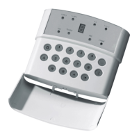
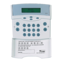
Remote Keypad
Supply Led on : Indicates AC supply and / or battery supply
12 SYSTEM FAULTS
There are 6 fault conditions automatically detected by the Atlas 4. The user is informed of a fault via the fault LED. This
LED will illumiate and an error tone will be emitted every 5 seconds when the panel is in day mode, Press a function key
to stop the error tone. The fault LED will remain on until the fault has been corrected.
To determine the fault go into the log by entering
. A symbol followed by 1-6 will be displayed.
1 Bell Fuse Failure
2 Auxiliary Fuse Failure
3 Battery Missing
4 Low Battery Voltage
5 Mains Failure
6 Telephone Line Failure
7 Spare
8 Event Report Failure
13 TECHNICAL SPECIFICATION
13.1 Power supply
Power input : 17V a.c.
Low voltage output : 13.2 Vdc fused, 1 Amp maximum Including Control Panel.
Low voltage output fuses : 1 Amp quick blow.
Battery charge voltage : 13.7 V d.c.
Rechargeable battery capacity : 12V sealed lead acid, 2.8 to 6 AH.
13.2 Control PCB
Current consumption
(day mode) : 130mA.
(set mode) : 130mA.
(alarm) : 130mA.
Auxiliary DC output supply : Regulated 13.2V d.c. for use with PIR, microwave and shock sensors.
Bell : 500mA.
PR1 : 250mA.
Alarm bell time : 2 to 20 minutes (software programmable).
Zone type : Normally closed loops which activate when opened or short circuit.
Zone loop current : 0.97mA max.
Zone activation resistance : 6.9K Ohms (minimum).
Zone loop activation timer : 0.35 seconds.
Exit timer : 2 to 255 seconds.
Entry timer : 2 to 255 seconds.
13.3 Mechanical
Dimensions : 223 x 205 x 78 mm.
Colour : White (grey export).
13.4 Environmental
Operating temperature : 0 to +40
0
C (+32 to +104
0
F).
Storage temperature : -20 to +60
0
C (-4 to +172
0
F).
13.5 Cleaning
DO NOT use strong detergents to clean this control panel. To remove any dirt or grime, wipe with a clean damp cloth
ONLY
 Loading...