95-8746
8
3.1
WIRING PROCEDURE
Ensure that all cables are terminated properly.
Conductor insulation should be stripped off with a
bare conductor length of 0.28 inch (7 mm). Ensure
that cable shield is properly terminated and that
bare shield wire is not allowed to accidentally
contact the metal housing or any other wire.
Use the following instructions when wiring the 30-
3013 detector:
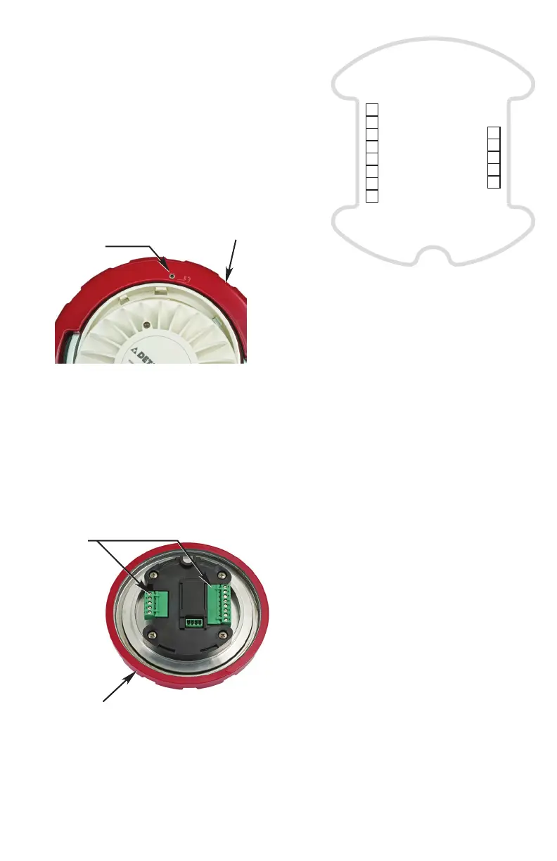
1. Slightly loosen the three setscrews located
on the retaining ring (see Figure 7).
2. Unscrew the retaining ring to gain access
to the wiring terminals (see Figure 8), and
complete the installation of the system
conduit. Feed the external wiring through
the remaining junction box entry or M25
to 3/4 inch adapter. When installing the
junction box, use care not to damage the
wires and refrain from twisting them.
3. Connect the external wiring to the
appropriate terminals.
– Figure 9 shows the wiring terminals.
– Figure 10 shows the ground lug
locations.
– Figures 12 and 13 show wiring for single
detector configurations.
– Figures 14 and 15 show wiring for multiple
detector configurations.
4. Re-install the assembly. Use the alignment
guide (see Figure 11) to align the retaining
ring with the junction box.
5. Screw the retaining ring on to the junction
box and re-tighten the three setscrews.
RELAY
OUTPUTS
A2683
– mA
– Vin
+ Vin
– Vin
+ Vin
5
4
3
2
1
POWER
SUPPLY &
0-20 mA OUTPUT
P11
P5
NO AUX
COM AUX
NC AUX
NO ALARM
COM ALARM
NC ALARM
COM FAULT
NO FAULT
1
2
3
4
5
6
7
8
Figure7—Setscrew Location
SET SCREWS (3)
RETAINING RING
Figure9—30-3013 Wiring Terminals
Figure8—Location of Wiring Terminals
RETAINING RING
WIRING
TERMINALS