3
95-8746
3.1
Appendix A - FM
Appendix B - CSA
Appendix C - IECEx
OPERATION
WARM UP
When the detector is initially powered up, a warm-
up period of one – two (1-2) seconds is allotted
for internal checks and communication. During
this time, the LED is off and the current level is
3 mA. After the checks are completed, normal
operation will be indicated by the LED flashing
every four seconds (current level is 4 mA).
If the detector is unable to reach the normal
operating mode, the warm-up period may extend
to five seconds, followed by a critical fault or an
advisory fault (see Table 1 for all current levels).
If the problem persists, check for any loose wiring
connections, ensure that the voltage supply is
sufficient, and cycle power if necessary.
OUTPUTS
Relays
The 30-3013 detector is furnished with smoke
alarm, fault, and auxiliary relays. All three relays
are rated to 5 amperes at 30 Vdc.
The smoke alarm relay has a single set of
terminals and normally open / normally closed
contacts, and normally de-energized operation.
The fault relay has a single set of terminals
and normally open contacts, and normally
energized operation.
The auxiliary relay has a single set of terminals
and normally open / normally closed contacts,
and normally de-energized operation.
IMPORTANT
The auxiliary relay functions as pre-alarm.
0 to 20 mA Output
This 30-3013 provides a 0 to 20 mA dc current for
transmitting detector status information to other
devices. The circuit is wired in a non-isolated
configuration and can drive a maximum loop
resistance of 300 ohms from 12 to 17.9 Vdc, 500
ohms from 18 to 19.9 Vdc, and 600 ohms from
20 to 30 Vdc. Table 1 defines the current levels
and corresponding detector status. The output
is calibrated at the factory, with no need for field
calibration.
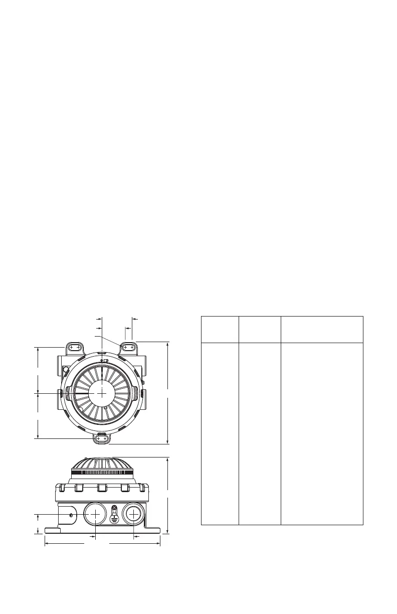
Figure2—30-3013 Dimensions in Inches (cm)
Table1—Detector Status Conditions Indicated by Current Level
Current
Level
(±0.3 mA)
Detector
Status
Recommended Action
0 mA Power Fault Verify 12-30 Vdc is
applied to detector
1 mA Critical
Fault
Cycle power. If fault
doe not clear or returns,
replace sensor module
or return to factory for
service.
2 mA Power
Advisory
(<12 Vdc)
Input power at detector is
<12 Vdc. Increase power
supply to 12-30 Vdc.
3 mA Warm up -
4 mA Normal -
6 mA Advisory
Fault
Cycle power. If fault
doe not clear or returns,
replace sensor module
or return to factory for
service.
16 mA Pre-Alarm Smoke present at sub-
alarm level.
20 mA Smoke
Alarm
-
4.99 (12.67)
B2680
7.55 (19.18)
2X 3.80 (9.65)
6X R0.19
2X 1.75
(4.44)
3.75 (9.52)
4X 1.29 (3.27)
2X 2.50 (6.35)
7.55 (19.18)